NV8500 family Digital Routers • User’s Guide 51
2. Installation
Installing Backplanes
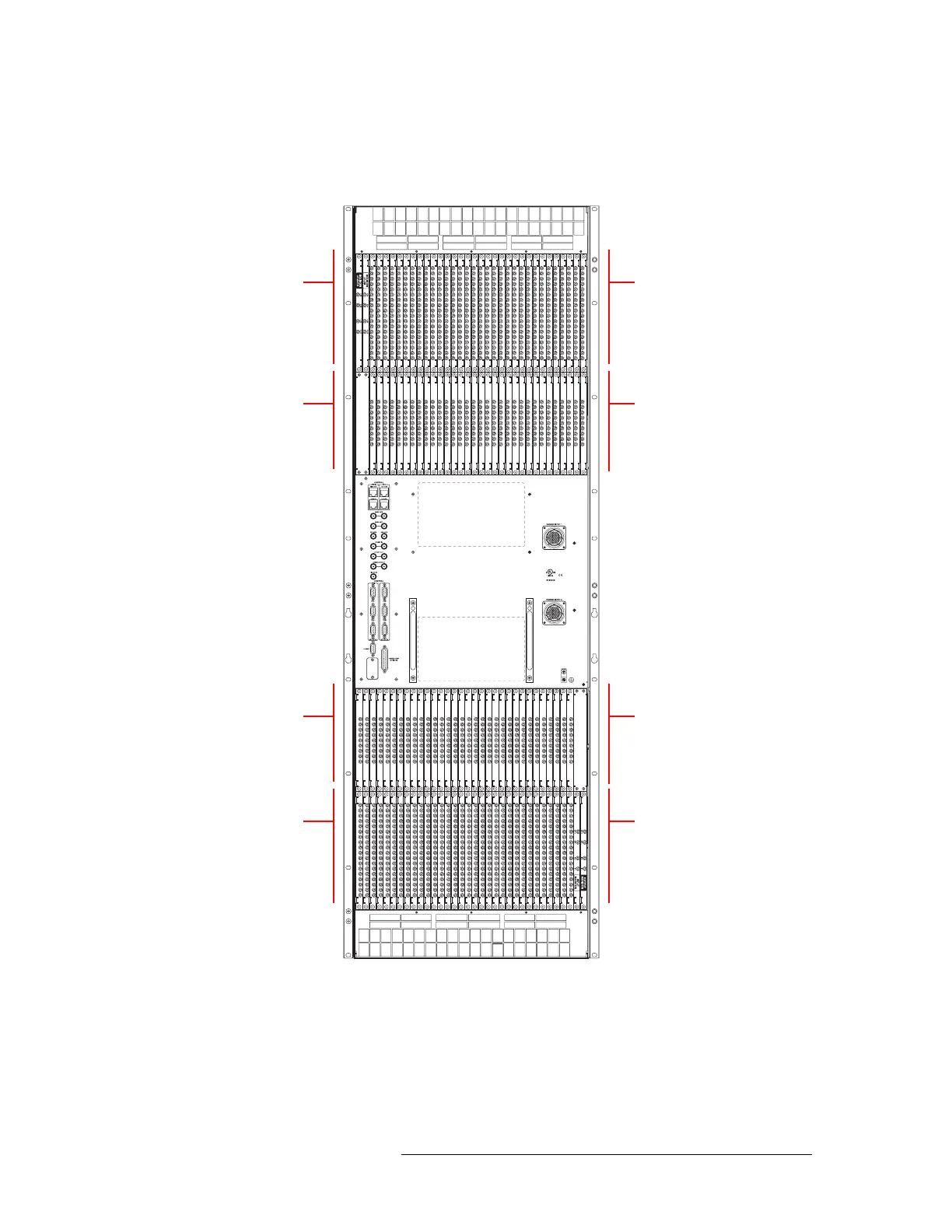
Figure 2-1, shows the backplane locations at the rear of an NV8576 router. For the NV8576-Plus,
the backplane location is identical, but the output backplanes have unique connectors for connect-
ing to a second NV8576-Plus router frame.
Figure 2-1. NV8576 Frame with Backplanes (Rear View)
Monitor
Backplanes (2)
Control card area
(no backplanes)
Output
Backplanes (32)
Input
Backplanes (32)
Unused
Monitor
Backplanes (2)
Input
Backplanes (32)
Output
Backplanes (32)