66 Rev 2.2 • 27 Mar 10
2. Installation
Making Signal Connections
3 For each output, connect to an output connector using a DIN 1.0/2.3 connector and 1855A
Belden cable, or an equivalent, or a LC connector and fiber optic cable, or a WECO connector
and coax cable.
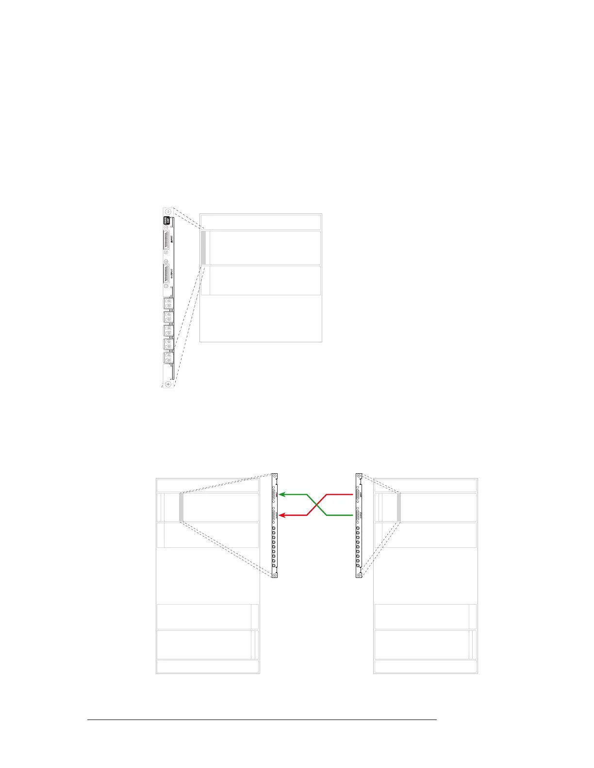
Important! LC expansion backplanes have 5 modules containing two LC connectors each for a
total of 10 possible connections. Do not connect to all 10 connections. You can only make a
total of 9 connections. When making LC connections, connect to the top 9 connectors, starting
from the top and working downward leaving the bottom connector empty. See Figure 2-12.
Figure 2-12. NV8280 LC Input Backplane (Rear View)
4 Connect the other end of the cable to the distribution destination for the outgoing signal.
5 Make expansion connections. Starting with the left-most backplane, connect from the top con-
nector of one backplane on the first router (Router 1) to the bottom connector of the corre-
sponding backplane on the second router (Router 2). .
Figure 2-13. Illustration of Expansion Connections
Inputs
Outputs
Expansion Backplanes
1
2
3
4
5
7
8
9
6
Not
used
Inputs
Outputs
Inputs
Outputs
Inputs
Outputs
Inputs
Outputs
Primary Secondary
Slot N Slot N
Expansion cable
(WC0121)