68 Rev 2.2 • 27 Mar 10
2. Installation
Making Signal Connections
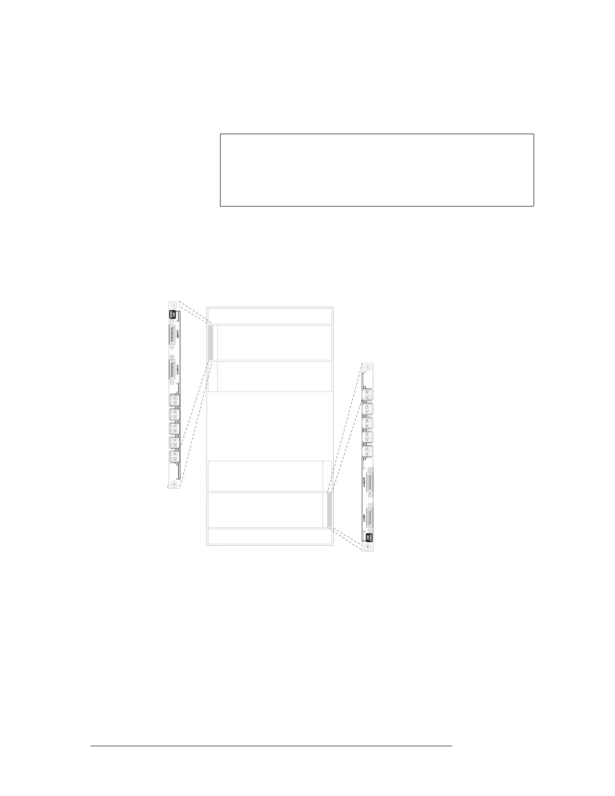
Important: LC expansion backplanes have 5 modules of two connectors each for a total of 10
possible connections. Do not connect to all 10 connections. You can only make a total of 9 con-
nections. Make LC connections:
In the upper portion of the router frame, leave the bottom connector empty.
In the lower portion of the router frame, leave the top connector empty. (Backplanes installed in
the lower portion of the frame are rotated 180° from those in the upper portion and “face” in the
opposite direction.)
Figure 2-14. NV8576-Plus LC Expansion Backplane (Rear View)
4 Connect the other end of the cable to the distribution destination for the outgoing signal.
5 Make expansion connections. Starting with the left-most backplane, connect from the top con-
nector of one backplane on the first router (Router 1) to the bottom connector of the corre-
Signal
Numbering
Note
Signals are numbered in ascending order from top-to-bottom. This is true
for backplanes in both the upper region and in the lower region of the
frame. Although the backplanes installed in the lower portion of the frame
are rotated 180° from those in the upper portion and “face” in the opposite
direction, the signal numbering is identical.
Inputs
Outputs
Inputs
Outputs
Expansion Backplanes
1
2
3
4
5
7
8
9
6
Not
used
1
2
3
4
5
7
8
9
6
Not
used