NV8500 family Digital Routers • User’s Guide 69
2. Installation
Making Signal Connections
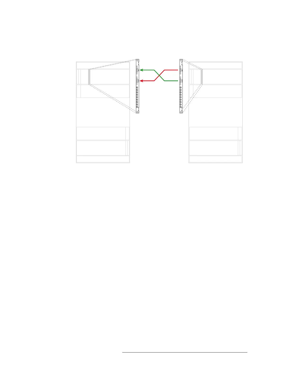
sponding backplane on the second router (Router 2). Repeat until all expansion connectors are
connected. .
Figure 2-15. Illustration of Expansion Connections
Make sure that the connectors are positioned in the upper portion of the router frame as follows:
• Black side of connector faces right.
• Silver side of connector faces left.
Inputs
Outputs
Inputs
Outputs
Inputs
Outputs
Inputs
Outputs
Primary Secondary
Slot N Slot N
Expansion cable
(WC0121)