NV8500 family Digital Routers • User’s Guide 71
2. Installation
Making Router Control System Connections
(i.e., backup system) or to set up dual control, if desired. For a detailed description of the serial con-
trol connections, see Router Control System Connections
on page 32.
In order for the router to communicate with the router control system through a serial connection,
Comm port and Baud rate settings need to be set in the control card. (See the UniConfig User’s
Guide.)
Serial control connections use SMPTE 207M DE9 connectors and serial (RS-422/489) cable.
How to Make Serial Connections to the Control System
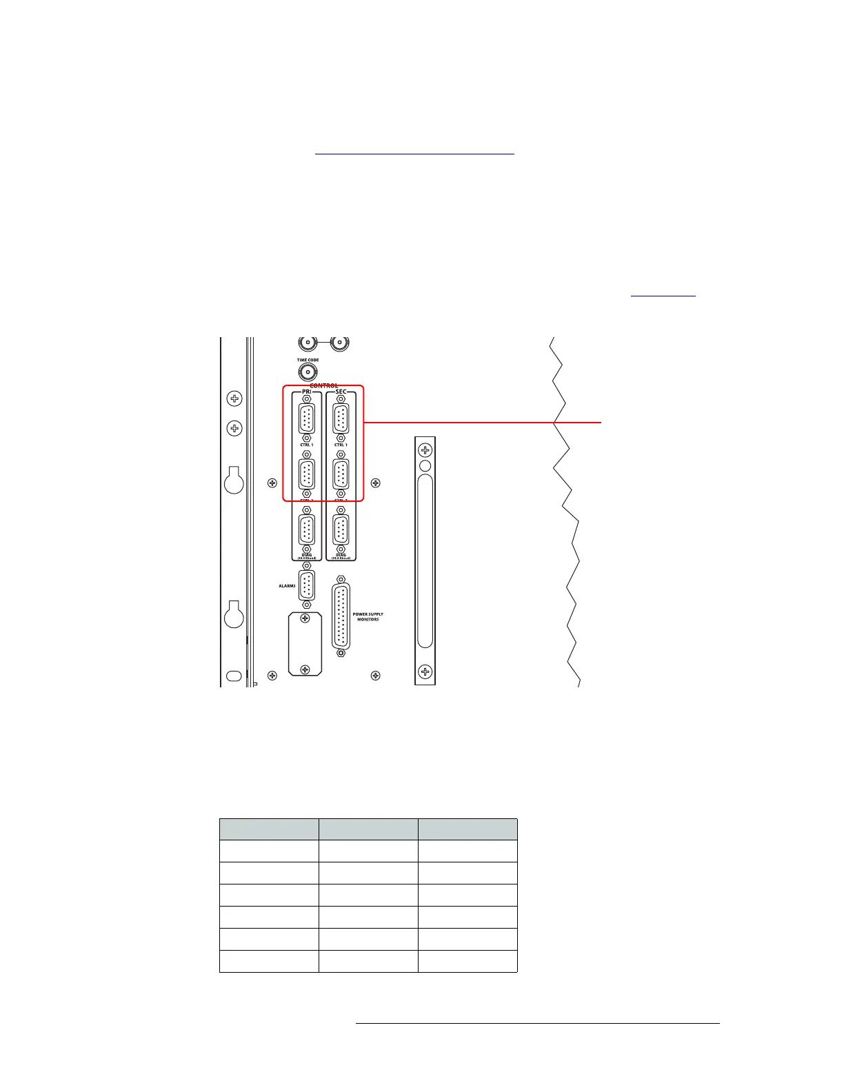
1 Locate the serial control connections on the rear of the router, as shown in Figure 2-16
. Serial
control connections are labeled ‘PRI’ for the primary control card and ‘SEC’ for the secondary
control card.
Figure 2-16. Serial Connections to Router Control System
2 Connect to the ‘CTRL 1’ connection in the ‘PRI’ section using a DE9 connector and serial
cable.
3 Connect the other end of the serial cable to the (primary) router control system using a DE9
connector.
The following lists the pin wiring for the DE9 connectors:
Serial Connections to
Control System
Control End Pins Router End
Ground 1 Ground
Rx– 2 Tx–
Tx+ 3 Rx+
Tx Common 4 Rx Common
N/C 5 N/C
Rx Common 6 Tx Common