Page 5 of 5
Miri Technologies, 2 Fellowship Road, Gnangara, Western Australia 6077 | Tel: +61 89 409 8998 | www.miri.com.au
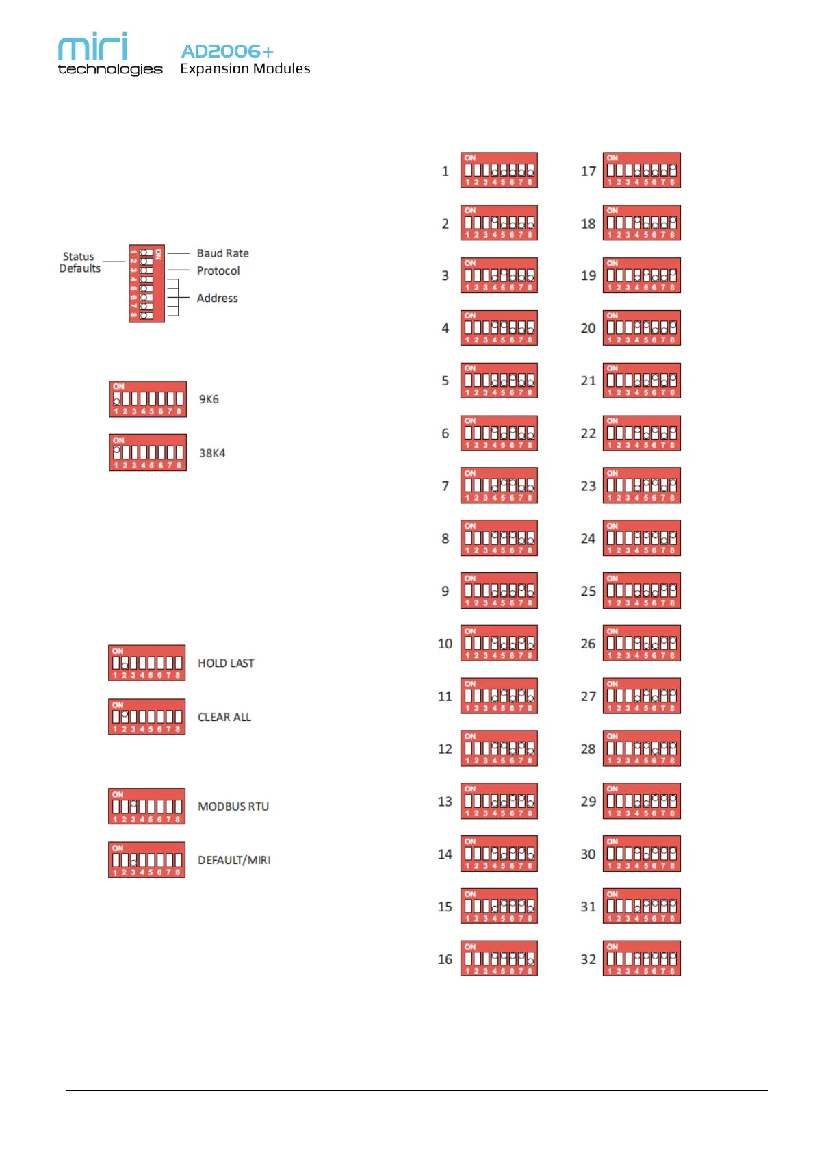
3. DIP Switch Settings
The DIP Switches located at the top of each
expansion module configure the module settings.
The function of each switch is shown below.
DIP Switch Operation
Set the Baud Rate
Note: Power cycle required for change to take effect.
Set the Status Defaults
In the event of loss of communications, the digital and
analog outputs will either default to a “HOLD
LAST” or “CLEAR ALL” status according to the switch
settings below.
Select the Protocol
DEFAULT/MIRI - The default setting is Miri protocol
which would normally be used when driving only
expansion modules via RS485.
MODBUS - Modbus protocol is usually used where
other third party Modbus devices are also connected
to the RS485 Multi-Drop Network. Please note that
this can only be done at 9600 or 38400 baud, so the
third party MODBUS devices must be capable of one
of these baud rates.
Configure the Polling ID
In an RS485 Multi-Drop network, whether the
protocol is Miri or MODBUS, each Expansion Module
will need a unique ID. The DIP Switch settings above
let you do this.