Do you have a question about the MIRI AD2006 and is the answer not in the manual?
Explains how to construct the AD2006 part number based on options and features.
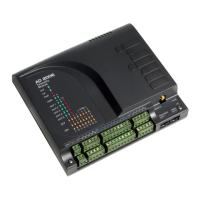
Describes the physical layout and ports of the AD2006 telemetry module.
Explains the function of various LEDs on the AD2006 module for status indication.
Details the configuration options for the AD2006 module's 8 analog input channels.
Describes the two versions (Low/High Voltage) of AD2006 digital inputs and their specifications.
Explains how digital inputs can be configured as pulse counters up to 5KHz.
Details the configuration options for the four digital outputs as relay or transistor outputs.
Details the function and pinout for Port 1, used for external data radios (FFSK or RS232).
Describes the use of Ports 2 and 5 for RS232 connections to third-party devices.
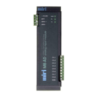
Explains Port 3's function as an RS485 multi-drop serial connection for expansion modules.
Notes Port 4 is intended for use as a programming port for the AD2006 module.
Describes the Ethernet option for Port 5, supporting Modbus TCP or Miri protocols.
Details the AD2006 modules' internal radio options (UHF/VHF) and default configuration.
Explains how to configure the module for external FFSK or RS232 radios via jumpers.
Lists available baud rate options for radio communication configuration on the AD2006 module.
Explains how to configure channels 5-8 as 4-20mA analog outputs with an installed board.
Describes setting analog input channel 8 to monitor the module's supply voltage.
Details configuring analog input channel 8 to provide a 5V source for field sensors.
Provides mounting arrangements and dimensions for vertically polarised 450-470 MHz antennas.
Illustrates the wiring for digital outputs, digital inputs, and analog inputs of the module.
Explains the module's installation using the mounting bracket and required clearances.
| Brand | MIRI |
|---|---|
| Model | AD2006 |
| Category | Control Unit |
| Language | English |