EasyManua.ls Logo

MIRI AD2006+ - User Manual

MIRI AD2006+
7 pages
Print Icon
To Next Page IconTo Next Page
Loading...
EXPANSION MODULES
QUICKSTART MANUAL
(August 2020)
PLEASE ENSURE THAT YOU HAVE THE CORRECT POWER SUPPLY VOLTAGE BEFORE POWERING UP THE MODULE.
The product warranty does not cover installation error.
Question and Answer IconNeed help?

Do you have a question about the MIRI AD2006+ and is the answer not in the manual?

Summary

Specifications

M-16 LN Input Module

Details specifications for the M-16LN Input Module, including voltage, impedance, and isolation.

M-16 HN Input Module

Details specifications for the M-16HN Input Module, including voltage, impedance, and isolation.

M8-AD Analog Input Module

M-16 TR Relay Module

M4-DA Analog Output Module

Wiring Detail

DIP Switch Settings

DIP Switch Operation

Describes the function of DIP switches for configuring module settings like Baud Rate, Protocol, and Address.

Set the Baud Rate

Instructions on setting the baud rate for expansion modules using DIP switches.

Set the Status Defaults

How to configure status default behavior (HOLD LAST or CLEAR ALL) during communication loss.

Select the Protocol

Guidance on selecting between Miri protocol and Modbus RTU using DIP switches.

Configure the Polling ID

Instructions for assigning a unique ID to each expansion module in an RS485 network.

Overview

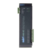
The AD2006+ is a series of expansion modules designed for DIN rail mounting, eliminating the need for additional DIN rail mounting terminals. These modules are driven from the RS485 port of an AD2006+ module or via an M232-485 converter if using the RS232 port of an AD2000 module. Up to 32 expansion modules can be driven from a single AD2006+ module. The RS485 bus allows modules to be located up to 1.5km from the AD2006+ telemetry module. An option to run Modbus on the RS485 bus is provided, allowing expansion modules to operate with third-party Modbus devices on a multi-drop RS485 bus. The protocol selection in MiriMap must match the DIP switch settings on the expansion modules. Other typical software settings include "Interface - Expansion Modules," "Polling - Continuous," "RTS during Tx must be checked," and a "Baud rate - 38.4k (default)."

The AD2006+ series includes several module types:

M-16LN Input Module

This module provides 16 optically isolated inputs with an input voltage range of 10-35 Volts AC or DC. The input impedance is 4k7 Ohms. It features two separate groups of 8 commons and offers 3.5kV isolation. The module operates on a 10-30VDC supply. Its power consumption is 200mW when no inputs are driven and 1.2W when all inputs are driven.

M-16HN Input Module

Similar to the M-16LN, this module also offers 16 optically isolated inputs but with a higher input voltage range of 70-130 Volts AC or DC. The input impedance is 27k Ohms. It also has two separate groups of 8 commons and 3.5kV isolation. The supply voltage is 10-30VDC, and its power drain is 200mW with no inputs driven and 1.2W with all inputs driven.

M8-AD Analog Input Module

This module provides 8 analog input channels, which are common-grounded. It supports input current ranges of 0-20mA or 4-20mA and input voltage ranges of 0-5V or 1-5V. The input impedance is 250 ohms in current mode. It offers a resolution of 12 bits and an accuracy and linearity of 0.1%. The module operates on a 10-30VDC supply and has an idle power drain of 200mW.

Usage Features for M8-AD Analog Input Module:

  • Range Selection: The analog input range options are selected via jumpers J9 and J10, offering three possible options (4-20mA/1-5V, 0-20mA/0-5V, or 0-1V). The selected range applies to all analog input channels. The factory default setting is 4-20mA / 1-5V.
  • Current / Voltage Selection: Individual analog input channels (J1 through J8) can be configured for either current or voltage inputs. Jumper installation sets a channel to current mode, while no jumper sets it to voltage mode. The factory default setting is all channels configured as current inputs.

M-16TR Relay Module

This module features 16 relays, each capable of switching 2 Amps at 30VDC or 240VAC. It has two separate groups of 8 commons, with a total output capability of 10 Amps per common. The module provides 3.5kV isolation and operates on a 10-30VDC supply. Its power drain is 200mW with no outputs driven and 2W with all outputs driven.

M4-DA Analog Output Module

This module offers 4 analog output channels with a common ground. The output current range is 4-20mA. The load impedance is 250 Ohms at 12V or 500 Ohms at 24V. It provides a resolution of 16 bits and an accuracy and linearity of 0.1%. The module operates on a 10-30VDC supply and has an idle power drain of 200mW.

General Usage Features:

  • DIP Switch Settings: Each expansion module has DIP switches at the top to configure its settings. These switches control Status Defaults, Baud Rate, Protocol, and Polling ID.
  • Baud Rate: Can be set to 9K6 or 38K4. A power cycle is required for changes to take effect.
  • Status Defaults: In case of communication loss, digital and analog outputs can be configured to either "HOLD LAST" or "CLEAR ALL" based on switch settings.
  • Protocol Selection: Options include "MODBUS RTU" or "DEFAULT/MIRI." The default Miri protocol is typically used when driving only expansion modules via RS485. Modbus protocol is used when other third-party Modbus devices are connected to the RS485 Multi-Drop Network, operating at 9600 or 38400 baud.
  • Polling ID: Each expansion module in an RS485 Multi-Drop network requires a unique ID, configured via DIP switches (IDs 1-32).

Maintenance Features:

  • Power Supply: Users must ensure the correct power supply voltage before powering up the module. The product warranty does not cover installation errors.

MIRI AD2006+ Specifications

General IconGeneral
BrandMIRI
ModelAD2006+
CategoryControl Unit
LanguageEnglish

Related product manuals