Page 2 of 5
Miri Technologies, 2 Fellowship Road, Gnangara, Western Australia 6077 | Tel: +61 89 409 8998 | www.miri.com.au
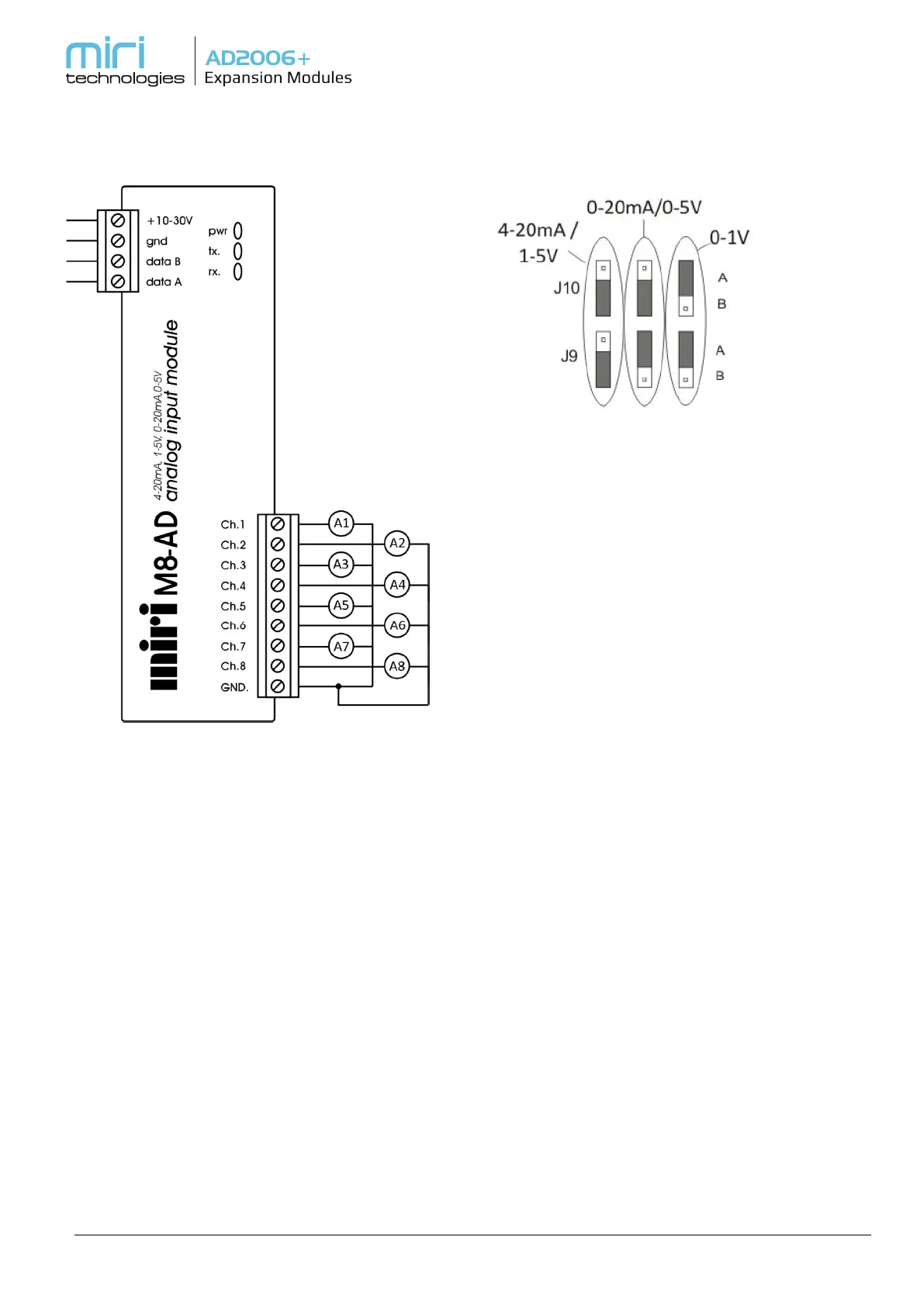
M8-AD Analog Input Module
4-20mA, 1-5V, 0-20mA, 0-5V
Inputs per Module 8 Channels – Common
Ground
Input Current Range 0-20mA or 4-20mA
Input Voltage Range 0-5V or 1-5V
Input Impedance 250 ohms (current mode)
Resolution 12 bits
Accuracy 0.1%
Linearity 0.1%
Supply Voltage 10-30VDC
Module Power Drain Idle 200mW
Range Selection
The analog input range options are selected via
jumpers J9 and J10, there are 3 possible options,
shown in the table below.
Note: The range selected will apply to all analog input
channels.
The factory default setting is 4-20mA / 1-5V.
Current / Voltage Selection
The analog input channels are configured by means
of J1 through J8, which correspond to the analog
channel numbers. They can be configured for any mix
of current or voltage inputs, but will all be scaled
according to the setting of jumpers J9 and J10.
Jumper settings for each channel (1 to 8)
Jumper: Channel is set to current.
No Jumper: Channel is set to voltage.
Default factory setting is jumpers (1 to 8) installed
such that all channels are configured as current
inputs.