7
©Miri Technologies - www.miri.com.au - Telephone: (+61 8) 9409 8998, Fax: (+61 8) 9409 9229
30 Buckingham Drive. Wangara, WA 6065 Australia
4. Options
Analog Output
An analog output board must be installed to utilise this option. This is a factory fitted option. When the analog board
is installed, any of the last four channels can be configured as 4-20mA outputs.
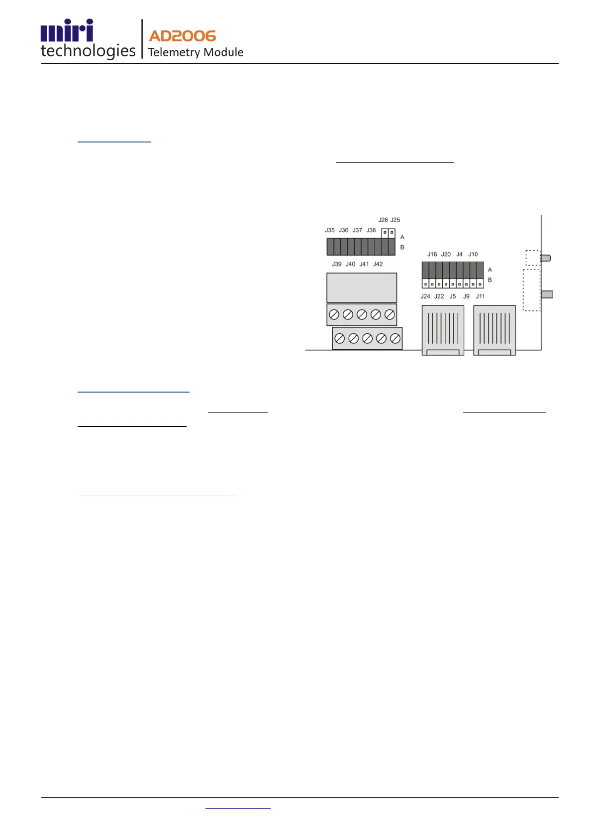
Channels 5 to 8 are selected as 4-20mA outputs by installing jumpers as follows;
• J4 – Position A (Channel 5)
• J5 – Position A (Channel 6)
• J20 - Position A (Channel 7)
• J22 & J16 - Position A (Channel 8)
Note - If channel 8 is configured as an analog output,
analog input 8 will still operate as a supply voltage
monitor, provided that J24 is selected in position A.
Note - J9, J10 and J11 are not relevant to the analog
channel options.
Power Supply Monitor
Analog input channel 8 is set by factory default to monitor the module’s supply voltage. This is particularly useful in
solar powered installations.
If channel 8 is required as a normal analog input channel then J24 is moved from position A to position B.
Voltage Source for Field Sensors
The analog input channel (8) can be configured as a 5V source to power field sensors to a maximum current supply of
20mA. To select this option, install jumpers;
• J16 - position B, &
• J22 - position A.
 Loading...