4
©Miri Technologies - www.miri.com.au - Telephone: (+61 8) 9409 8998, Fax: (+61 8) 9409 9229
30 Buckingham Drive. Wangara, WA 6065 Australia
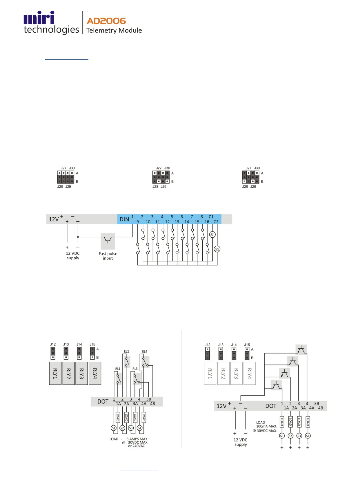
Pulse Counters
Each Digital Input may be used as a pulse counter up to 5Hz. The first two inputs can be configured as high speed
pulse counters up to 5KHz (equal mark space ratio).
• Where the inputs are used as slow counters (to 5Hz), the inputs are usually referred to the digital input
common.
• Where the fast pulse counters are used, the inputs are referred to the module 0V supply (ground).
The digital inputs will then accept inputs from common emitter transistors, FETs or reed switches etc. as shown below.
The factory default setting is for all inputs to be configured as digital inputs / slow counters. The following jumper
settings apply where inputs 1 or 2 are required to be fast counters.
Jumper Configurations
Digital Input Wiring
Digital Outputs
Each of the four Digital Outputs may be individually configured as an isolated relay or common emitter transistor.
Isolated Relay Configuration (factory default) Common Emitter Configuration
With all jumpers J12 - J15 in position A, the module is
configured for 2 SPST and 2 SPDT relay outputs.
With all jumpers J12 - J15 in position B, all outputs are
common emitter transistors.
All inputs
DINs (factory
default)
(OR)
DIN1 –
Fast Pulse
(OR)
DIN2 –
Fast Pulse
 Loading...