2.INSTALLATIONINSTRUCTIONS
Tools and Parts
Gather the required tools and parts listed below before starting installation. Read and follow the instructions
.
Required tools
Level - Caulking gun and waterproof caulking compound
Drill - Flat-bladed screwdriver
Drill bit of 1/8’’ (3 mm) - Jigsaw or reciprocator saw
Pencil - Phillips screwdriver
Pliers - Duct flanges
Measuring tape or ruler - Tin snips
Necessary parts
Round metal drain pipe system of 6”
(15.2
cm)
in diameter
Location requirements
IMPORTANT:
Observe that all local and National codes and regulations are met
.
Entrust the installation of the hood to a qualified installer. It is the installer's responsibility to respect the
separation clearances specified on the nameplate of the unit. The unit's rating plate is located behind the filter
on the left rear wall of the hood. Install the range hood away from any area that is exposed to drafts, such as
windows, doors and heating vents.
Follow the dimensions indicated for openings to be cut in cabinets. These dimensions provide a minimum
clearance. Before making cut-outs, refer to the instructions of the cooktop or range, above which you will place
the hood.
The location must be equipped with a grounded electrical outlet. See '’Electrical Specifications'' for more
information. The hood is configured for installation with a discharge to the outside through the roof or wall.
Make sure to seal each opening cut in the ceiling or wall for the installation of the range hood.
Installation
in a
m
o
bile home
The installation of this range hood must meet the requirements of national and local standards and codes.
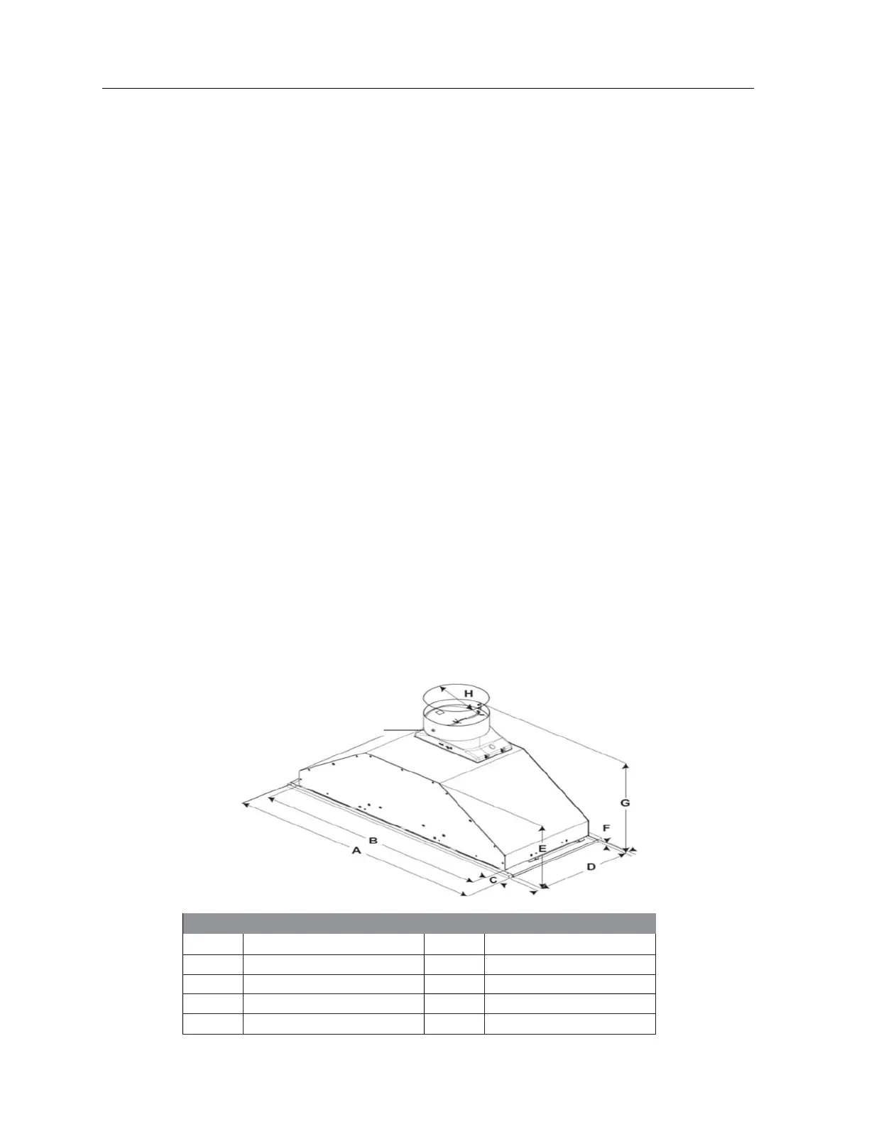
Dimensions
of the unit
Built-In Hood 27.6‘’ (70.1 cm)
Dimension Dimension
A
27 1/2’’ (68.6 cm)
E
9 7/8’’ (25.1 cm)
B
26’’ (66 cm)
F
5/8’’ (1.6 cm)
C
5/8’’ (1.6 cm)
G
12 3/8’’ (30.43 cm)
D
10 1/4’’ (25.4 cm)
H
6’’ (15.25 cm)
5