3
Assembly
•
•
•
•
CAUTION:
•
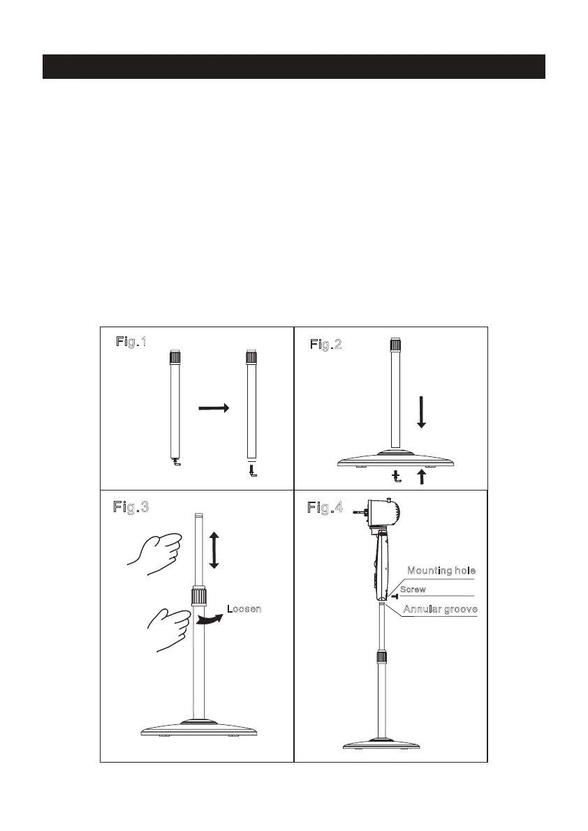
Unscrew the 7-shape Bolt from the Extension Pole. (Fig.1)
Insert the extension pole into the chassis and tighten the 7-shape Bolt (Fig.2)
From the extension pole loosen the height adjustment ring and adjust the internal pole to
the desired height. (Note: If you can’t nd the internal pole, it must inside the extension
pole. You can pull it out from the extension pole.) (Fig.3)
To attach the head unit to the internal pole, loosen the thumb screw on the bottom of the
head unit. Place the head unit on the internal pole and tighten the thumb screw in
alignment with the groove on the internal pole. (Fig.4)
Height adjustment ring must be fully fastened before the assembly of the
motor section to the internal pole.
CONTROLS AND OPERATIONS
Annular groove
Mounting hole
Screw
Fig.3
L
o
o
seen
F
ig.4
Fig
.
1
Fig.2