11
GB
D
F
INL
E
PGRRUTR
<Permissible Lengths>
1 M-NET Remote controller
• Max length via outdoor units: L
1+L2+L3+L4 and L1+L2+L3+L5 and L1+L2+L6
=
500 m [1640 ft] (1.25 mm
2
[AWG 16] or more)
• Max transmission cable length: L
1 and L3+L4 and L3+L5 and L6 and L2+L6
=
200 m [656 ft] (1.25 mm
2
[AWG 16] or more)
• Remote controller cable length: r
1, r2, r3, r4
=
10 m [32 ft] (0.3 to 1.25 mm
2
[AWG 22 to 16] )
If the length exceeds 10 m [32 ft], use a 1.25 mm
2
[AWG 16] shielded wire. The length of this section (L8) should be included in the
calculation of the maximum length and overall length.
2 MA Remote controller
• Max length via outdoor unit (M-NET cable): L1+L2+L3+L4 and L1+L2+L6
=
500 m [1640 ft] (1.25 mm
2
[AWG 16] or more)
• Max transmission cable length (M-NET cable): L
1 and L3+L4 and L6 and L2+L6
=
200 m [656 ft] (1.25 mm
2
[AWG 16] or more)
• Remote controller cable length: c
1 and c1+c2+c3 and c1+c2+c3+c4
=
200 m [656 ft] (0.3 to 1.25 mm
2
[AWG 22 to 16] )
h. The group setting operations among the multiple indoor units is done by the remote controller (RC) after the electrical power has been turned on.
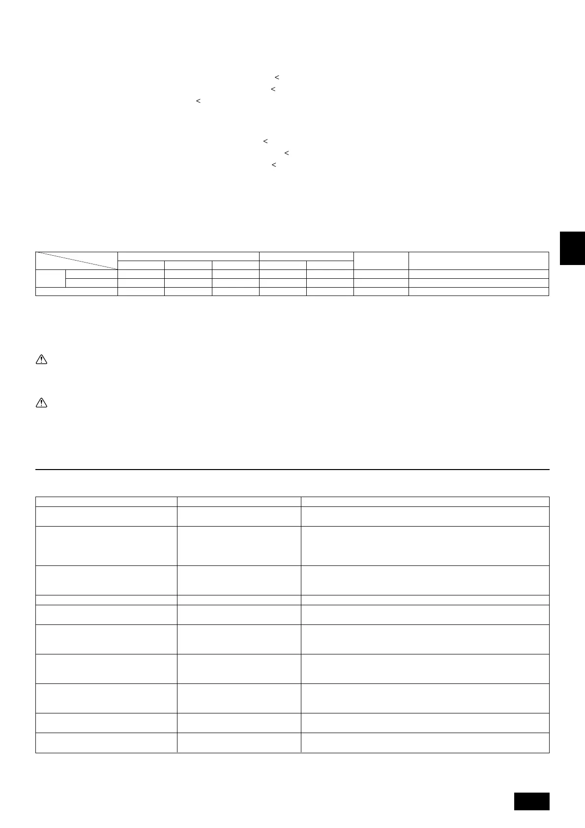
9.4. Wiring of main power supply and equipment capacity
Schematic Drawing of Wiring (Example)
[Fig. 9.4.1] (P.4)
A Switch (Breakers for Wiring and Current Leakage) B Outdoor Unit
C Pull Box D Indoor Unit
Wire size for Main Power Supply and On/Off Capacities
1. Use a separate power supply for the outdoor unit and indoor unit.
2. Bear in mind ambient conditions(ambient temperature,direct sunlight, rain water,etc.) when proceeding with the wiring and connections.
3. The wire size is the minimum value for metal conduit wiring. The power cord size should be 1 rank thicker consideration of voltage drops.
Make sure the power-supply voltage does not drop more than 10 %.
4. Specific wiring requirements should adhere to the wiring regulations of the reglon.
Warning:
• Be sure to use specified wires to connect so that no external force is imparted to terminal connections. If connections are not fixed firmly, it may cause
heating or fire.
• Be sure to use the appropriate type of overcurrent protection switch. Note that generated overcurrent may include some amount of direct current.
Caution:
• Some installation site may require attachment of an earth leakage breaker. If no earth leakage breaker is installed, it may cause an electric shock.
• Do not use anything other than breaker and fuse with correct capacity. Using fuse and wire or copper wire with too large capacity may cause a malfunction
of unit or fire.
50A 100mA 0.1sec. or less
60A 100mA 0.1sec. or less
20A 30mA 0.1sec. or less
75A
75A
15A
60
75
15
60
75
15
8.4/8
13.3/6
0.41/22
8.4/8
13.3/6
0.41/22
Indoor Unit
Main Cable
Switch (A)
Minimum Wire Size (mm
2
/AWG)
Branch Capacity Fuse
Breaker for Current Leakage
Model
Outdoor
Unit
80
100
–
–
0.41/22
Breaker for
Wiring (NFB)
Ground
10. Test run
10.1. The following phenomena do not represent trouble (emergency)
Display of remote controller
Normal display
Normal display
Normal display
Defrost display
No lighting
Heat ready
Normal display
“HO” flashes
Light out
Cause
This is not a trouble as it is just a selecting sound.
Because of the control operation of auto vane, it may change over to horizontal
blow automatically from the downward blow in cooling in case the downward
blow operation has been continued for 1 hour. At defrosting in heating, hot adjust-
ing and thermostat OFF, it automatically changes over to horizontal blow.
Ultra-low speed operation is commenced at thermostat OFF.
Light air automatically changes over to set value by time or piping temperature at
thermostat ON.
The fan is to stop during defrosting.
Fan is to run for 1 minute after stopping to exhaust residual heat (only in heating).
Ultra low-speed operation for 5 minutes after SW ON or until piping temperature
becomes 35°C, low speed operation for 2 minutes thereafter, and then set notch
is commenced. (Hot adjust control)
When the outdoor unit is being cooled and the refrigerant is resting, warming up
operation is performed for at least 35 minutes to warm the compressor.
During this time, only the fan operates.
System is being driven.
Operate remote controller again after “HO” disappear.
After a stop of cooling operation, unit continues to operate drain pump for three
minutes and then stops it.
Unit continues to operate drain pump if drainage is generated, even during a
stop.
Phenomenon
Indoor unit and BC controller generate sound
at the cooling/heating change over sometime.
The auto vane runs freely.
Fan setting changes during heating.
Fan stops during heating operation.
Fan does not stop while operation has been
stopped.
No setting of fan while start SW has been
turned on.
Outdoor unit does not operate by turning
switch on.
Indoor unit remote controller shows “HO” in-
dicator for about two minutes when turning
ON universal power supply.
Drain pump does not stop while unit has been
stopped.
Drain pump continues to operate while unit
has been stopped.
 Loading...