J
jacquelinepierceSep 3, 2025
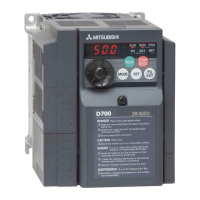
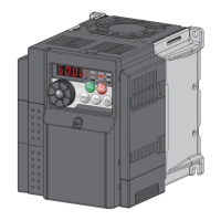
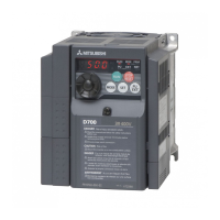
What does PU stop mean on Mitsubishi Electric Inverter?
- Jjessica23Sep 3, 2025
Stop with of the PU is set in Pr. 75 Reset selection/disconnected PU detection/PU stop selection. Turn the start signal OFF and release with .