Do you have a question about the Mitsubishi Electric FR-D720S SC EC and is the answer not in the manual?
| Series | FR-D700 |
|---|---|
| Model | FR-D720S SC EC |
| Input Voltage | 200-240V AC |
| Output Voltage | 3-Phase 200-240 VAC |
| Protection Class | IP20 |
| Cooling Method | Fan cooled |
| Enclosure | IP20 |
| Control Method | V/F Control |
| Frequency Range | 0 to 400 Hz |
| Overload Capacity | 150% for 60s |
| Protection Features | Overcurrent, Overvoltage, Undervoltage, Overheat |
| Communication | RS-485 |
| Ambient Temperature | -10°C to +50°C |
| Storage Temperature | -20°C to +65°C |
| Humidity | 95% RH or less (non-condensing) |
| Altitude | Up to 1000 m |
| Vibration | 5.9 m/s² |
Essential precautions to prevent electric shock hazards when handling the inverter.
Guidelines to prevent fire hazards related to inverter installation and operation.
Measures to prevent physical injury from inverter components or incorrect handling.
Instructions for safe transport and proper installation of the inverter unit.
Explanation of the FR-D700 SC inverter model naming convention and its components.
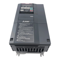
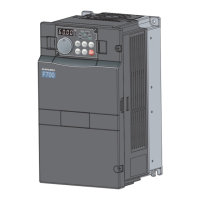
Detailed description of the inverter's appearance and internal structure, including key components.
Step-by-step instructions for safely removing and reinstalling the inverter's front cover.
Procedures for removing and reinstalling the inverter's wiring cover for access to terminals.
Guidelines for correctly mounting the inverter vertically to ensure proper heat dissipation and accessibility.
Considerations for designing and manufacturing inverter enclosures, including environmental factors.
Specifies environmental conditions required for inverter operation to ensure reliability and prevent failures.
Details minimum clearances around the inverter for heat dissipation and service accessibility.
Overview of system configuration, showing the inverter and its common peripheral devices and their connections.
Detailed diagram illustrating all main and control circuit terminal connections for the inverter.
Specifications and layout for connecting the main power circuit terminals of the inverter.
Detailed specifications for control circuit terminals, including input and output signals.
Essential precautions to ensure product longevity and prevent damage during operation or handling.
Step-by-step guide on how to perform settings and connections to drive the motor using the inverter.
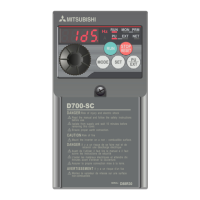
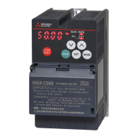
Detailed explanation of the operation panel's parts, indicators, and keys for controlling the inverter.
Overview of basic parameters for simple variable-speed operation and their initial settings.
How to control the inverter using the parameter unit (PU) via RUN key, digital dial, or external signals.
Procedures for operating the inverter using external signals connected to STF, STR, and other terminals.
Comprehensive listing of all parameters, their functions, initial values, and setting ranges.
Parameters for adjusting motor torque, including manual torque boost and slip compensation.
Settings to limit the maximum and minimum output frequencies for motor speed control.
Parameters for adjusting V/f characteristics based on load and applications.
How to set frequency using multi-speed settings, jog operation, or remote settings via external terminals.
Parameters for setting acceleration and deceleration times and patterns.
Parameters for motor protection, including overheat protection and applied motor selection.
Parameters related to DC injection brake, regenerative brake, and motor stopping methods.
Configuration of input and output terminals for various functions like start signals, frequency commands, and alarms.
Settings for selecting and displaying various monitor data on the operation panel and outputting signals via terminal AM.
Configuration for automatic restart and deceleration-to-stop functions during power interruptions.
Settings for retry functions and managing behavior during communication errors or phase failures.
Parameters for optimizing energy saving, including optimum excitation control.
Techniques to reduce motor noise, EMI interference, and mechanical resonance.
Configuration for frequency setting using analog voltage or current input signals.
Parameters to prevent misoperation, limit reset functions, and restrict parameter changes.
Settings for selecting the inverter's operation mode (PU, external, network) and command sources.
Comprehensive list of all operation panel indications for errors, warnings, and alarms.
Troubleshooting guide for common error messages displayed on the operation panel.
Procedures for resetting the inverter after a protective function has been activated.
Correspondence between digital characters and actual alphanumeric characters on the LED display.
Instructions on how to check and clear the recorded fault history of the inverter.
General troubleshooting steps for common operational issues like motor not starting or speed variations.
Daily and periodic inspection procedures to maintain the inverter and prevent faults.
Basic checks to be performed regularly to identify potential issues during operation.
Guidelines for periodic checks, especially for inaccessible areas and safety functions.
Detailed table outlining inspection items, intervals, and corrective actions for daily and periodic checks.
Information on how to check the estimated life of inverter components for preventive maintenance.
Procedures for checking the continuity and condition of inverter and converter modules using a tester.
Instructions for safely cleaning the inverter's exterior.
Guidance on periodic replacement of parts like cooling fans and capacitors based on life check.
Technical specifications for the FR-D700 SC series inverters, including electrical and environmental data.
Detailed specifications for the 1-phase, 200V class inverter models.
Detailed specifications for the 3-phase, 400V class inverter models.
General specifications applicable to all FR-D700 SC models, including control systems and I/O signals.
Mechanical dimensions and mounting information for various inverter models and parameter units.
Comprehensive list of all parameters with instruction codes for communication and operation.
Information on checking the serial number and understanding specification changes.
How to check and interpret the serial number format on the inverter's rating plate.