Do you have a question about the Mitsubishi Electric Got 1000 and is the answer not in the manual?
Precautions related to the design and potential failures of the GOT.
Precautions to be taken during the mounting of the GOT and option boards.
Precautions to be taken during the wiring of the GOT.
Precautions to be taken during test operations of the user creation monitor screen.
Precautions for starting up and maintaining the GOT unit.
Precautions to be taken when disposing of the product.
Precautions to be taken when transporting lithium batteries and GOT units.
General precautions for using the graphic operation terminal and its manual.
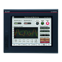
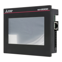
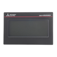
Highlights key features of the GOT, including performance and connectivity.
Outlines the basic steps before operating the GOT.
Describes the general configuration of the GOT and its components.
Lists and explains the components of the GOT model names.
Details general specifications like operating temperature, humidity, and vibration.
Provides detailed performance specifications for various GOT models.
Details the specifications of the built-in interfaces like RS-422, RS-232, USB, and CF card.
Details the power supply specifications for GOT units.
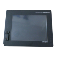
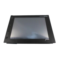
Identifies and describes the components on the front panel of the GOT.
Identifies and describes the components on the back panel of the GOT.
Information on UL and cUL standards applicable to the GOT.
Details requirements and precautions for conformance to the EMC Directive.
Specifies the internal dimensions of the control panel required for mounting the GOT.
Provides the dimensions required for cutting the panel to mount the GOT.
Specifies the required clearances from other devices when mounting the GOT.
Details the recommended control panel temperature and mounting angles for the GOT.
Step-by-step procedure for installing the GOT into a panel.
Details the wiring procedures for the power supply to the GOT.
Explains wiring practices inside and outside the control panel to prevent noise.
Information about applicable CF cards and their usage for data transfer.
Details the memory card adaptor for converting CF cards to memory cards.
Information on optional function boards that can be mounted on the GOT.
Details about the battery, its specifications, and replacement procedures.
Information on protective sheets for the GOT display section.
Information on the USB environmental protection cover for the GOT.
Information about applicable stands for fixing the GOT in a standing status.
Information about protective covers for oil to improve GOT's waterproof property.
Details the serial multi-drop connection unit for 1:N communication.
Information on the connector conversion adapter for multi-drop connections.
Explains how to execute utility functions by installing BootOS and Standard monitor OS.
Lists and describes the functions that can be set or operated on the utility screens.
Explains how to display setting screens for each utility via the main menu.
Describes setting communication interfaces, channel numbers, and drivers.
Details various communication parameters for communication devices.
Covers settings for opening screen time, screen save, language, and battery alarm.
Explains how to adjust the brightness and contrast of the display.
Covers settings for buzzer volume, security, utility call keys, and key sensitivity.
Details how to change the security level by inputting a password.
Explains how to specify the key position for calling the main menu of the utility.
Covers setting and displaying the GOT clock data and battery status.
Explains drive names and storage locations for OS, project data, and alarm data.
Describes how to display and manage OS information, including installation and uploading.
Details how to display, delete, copy, and manage project data files.
Explains how to display, delete, and copy alarm log files.
Covers the procedure for formatting CF cards or Internal SRAM.
Displays the amount of memory empty area and boot drive information.
Describes how to copy OS and project data to a memory card for backup or transfer.
Provides functions for PLC system status check and troubleshooting.
Explains how to monitor and change devices within a target controller.
Enables editing of sequence programs in ACPU/QCPU (A mode) and parameters.
Enables changing sequence programs and parameters in the FX PLC.
Carries out self-checks for GOT hardware or memory.
Performs write/read checks on Standard CF card, Flash memory, and Internal SRAM.
Checks display elements like missing bits, color, and figure shapes.
Confirms installed fonts in the GOT and checks character data display.
Checks for dead zones in the touch panel's minimum unit.
Checks communication between GOT and PLC and verifies connection hardware.
Displays error codes and messages when errors occur in GOT, controller, or network.
Displays the GOT's start time, current time, and operating hours.
Instructions for cleaning the GOT display section.
Lists the BootOS and Standard monitor OS necessary for executing utility functions.
Outlines necessary preparations for installing BootOS and Standard monitor OS.
Explains two methods for installing BootOS and Standard monitor OS using a CF card.
Provides guidance on installing different versions of BootOS and Standard monitor OS.
Details the installation process for CoreOS on the GOT.
Lists items for daily inspection of the GOT and its components.
Outlines yearly or half-yearly inspection items for the GOT.
Provides instructions on how to clean the GOT and precautions to take.
Explains battery status detection and replacement procedures.
Describes backlight shutoff detection and how to issue external alarms.
Explains how to identify error codes and system alarms on the monitor screen.
Lists error codes, messages, and their corresponding corrective actions.
Provides troubleshooting steps for issues related to bus connections.
Describes countermeasures for when the GOT does not display the monitor screen.
Covers procedures for starting the GOT, including power-off and communication.
Provides external dimensional diagrams for GT1155-QTBD, GT1155-QSBD and GT1150-QLBD.
Provides external dimensional diagrams for GT1155-QTBDQ, GT1155-QSBDQ and GT1150-QLBDQ.
Provides external dimensional diagrams for GT1155-QTBDA, GT1155-QSBDA and GT1150-QLBDA.
Provides external dimensions for the memory board.
Provides external dimensions for GT05-50STAND and A9GT-50STAND.
Provides external dimensions for the GT01-RS4-M serial multi-drop connection unit.
Provides external dimensions for the GT10-9PT5S connector conversion adapter.
Provides external dimensions for communication cables like GT01-C30R4-25P and GT01-C R4-8P.
Provides external dimensions for communication cables like GT01-C30R2-25P, GT01-C30R2-9S, and GT01-C30R2-6P.
Provides external dimensions for bus connection cable connectors.
Details the applicability of utility functions based on GOT type and software.
Details the usage conditions of utility functions for various setting items.
Details utility function usage for OS, Project, Alarm, and Recipe information.
Details utility function usage for Logging, Operation log, Hard copy, and Memory card.
Details utility function usage for Debug/Self check functions like System monitor and Ladder monitor.
Details utility function usage for Debug/Self check and Maintenance report.
Lists relevant models for battery transportation, specifically the GT11-50BAT.
Outlines general guidelines for transporting products, emphasizing compliance with regulations.
| Series | GOT1000 |
|---|---|
| Display Type | TFT Color LCD |
| Power Supply | 24 VDC |
| Touch Technology | Resistive |
| Operating System | Proprietary |
| Communication Interfaces | RS-422/485, RS-232, Ethernet |