Do you have a question about the Mitsubishi Electric M700V Series and is the answer not in the manual?
| Brand | Mitsubishi Electric |
|---|---|
| Model | M700V Series |
| Category | Recording Equipment |
| Language | English |
Details the NC axis, spindle, PLC axis, and auxiliary axis, generically called control axes.
Defines the number and maximum quantity of part systems that can be controlled.
Explains control axes and various operation modes like Tape, Memory, MDI, and Server modes.
Covers least command increment for input settings and movement commands, defining resolution and units.
Describes switching between metric and inch unit systems for settings, display, and feed operations.
Details various G-code program formats for lathes and machining centers, including special Mitsubishi formats.
Explains decimal point input types (I, II), absolute/incremental commands, and diameter/radius designation.
Enables high-speed positioning using programmed movement commands, taking the shortest path.
Covers linear interpolation at cutting feed rate and circular interpolation using center or radius designation.
Includes exponential, spline, NURBS, and 3-dimensional circular interpolation for machining complex curves and shapes.
Details rapid traverse, cutting, and manual feed rates, including override and acceleration/deceleration settings.
Explains feed per minute (asynchronous) and feed per revolution (synchronous) input methods, including inverse time feed.
Covers rapid traverse, cutting feed, and 2nd cutting feed overrides, plus override cancel functionality.
Describes automatic acceleration/deceleration patterns and rapid traverse constant inclination methods.
Details thread cutting, variable lead thread cutting, synchronous tapping, and chamfering functions.
Explains manual rapid traverse, jog feed, incremental feed, handle feed, and manual feed rate B operations.
Describes dwell function for temporarily stopping machine movement for a specified time using G04 command.
Details memory capacity in kB and number of programs stored for various configurations.
Covers program erasing, filing, copying, editing, and mass editing functions.
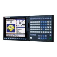
Describes the configuration of the setting and display unit, including setting and keyboard sections.
Explains operation input, value settings, screen switching, menus, guidance, and error handling.
Details status display, clock display, operation screen, preparation, edit, diagnosis, and maintenance screens.
Covers input/output of machining programs, tool offset data, common variables, parameters, and history data.
Details various interfaces like RS-232C, IC Card, Ethernet, Hard Disk, USB Memory for data transfer.
Explains passing data between host computer and CNC using computer link functions.
Covers spindle control, digital/analog interfaces, coil switches, encoder inputs, S code output, and constant surface speed control.
Explains T command for designating tool number and tool compensation numbers (length, wear).
Covers M commands for auxiliary functions like spindle rotation, coolant control, and independent M code outputs.
Details tool length compensation and tool position offset, including methods for additional axes.
Explains tool radius compensation (2D and 3D), tool nose radius compensation, and automatic decision of compensation direction.
Specifies the number of tool compensation sets and covers compensation memory for shape and wear amounts.
Explains machine, workpiece, local, and external coordinate systems and their settings.
Covers manual and automatic reference position return, including reference position check and tool change position return.
Includes optional block skip, skip addition, and single block execution for program control.
Covers dry run, machine lock, miscellaneous function lock, graphic checks, and machining time computation.
Details program search, sequence number search, verification stop, program restart, and automatic operation start.
Explains manual interruption, automatic operation handle interruption, manual absolute switch, and cycle retracts.
Covers subprogram control, figure rotation, scaling, axis name switch, macro programs, fixed cycles, and mirror image functions.
Details high-speed machining modes, high-accuracy controls, spline interpolation, and SSS control for improved machining performance.
Covers backlash, pitch error, relative position error, external coordinate system, and ball screw thermal expansion compensation.
Explains SHG control, dual feedback, lost motion compensation, OMR-FF, arc speed clamp, and vector accuracy interpolation.
Covers skip function, tool length measurement, workpiece coordinate offset, and position measurement.
Details tool life management I, II, and III, including number of tool life management sets.
Includes programmable current limitation and auto power off functions.
Covers emergency stop and data protection key functions for machine safety.
Details NC warnings, alarms, operation stop causes, and emergency stop causes.
Covers stroke end, stored stroke limits (I, II, IIB, IC), stroke check, and chuck/tailstock barrier checks.
Includes operation history, data sampling, NC data backup, MELDASNET, servo tuning, system setup, and error detection.
Details servo motor and spindle specifications for various drive systems like MDS-D/DH, MDS-DM.
Lists servo motor specifications for feed axes across different models and series.
Lists spindle specifications for various drive systems like MDS-D-SP, MDS-DH-SP.
Details auxiliary axis control servo motors for index/positioning and other types.
Lists power supply specifications including MDS-D-CV, MDS-DH-CV, AC Reactor, and Ground Plate.
Covers built-in PLC processing modes, functions, parameters, development tools, and protection.
Explains servo OFF, axis detachment, synchronous control, and inclined axis control for machine components.
Details arbitrary feed, circular feed in manual mode, and PLC axis control.
Covers CNC control signals, status signals, PLC windows, external search, and communication interfaces.
Lists additional DI/DO, remote I/O, and MITSUBISHI CNC Machine Operation Panel specifications.
Explains CC-Link, DeviceNet, and FL-net communication methods for connecting PLC and NC systems.
Covers customization using NC Designer, data storage, user-defined keys, EZSocket I/F, APLC, and custom API library.
Includes system lock, CNC remote operation tools (NC Monitor, NC Explorer), automatic operation lock, and others.
