Do you have a question about the Mitsubishi Electric M70V Series and is the answer not in the manual?
| Spindle Control Axes | Up to 4 axes |
|---|---|
| Interpolation | Linear, circular, helical |
| Communication Interfaces | Ethernet, RS-232, USB |
| Programming Language | G-code |
| Operating Temperature | 0 to 45°C |
| Storage Temperature | -20 to 60°C |
Imminent fatalities or serious injuries if handling is mistaken.
Fatalities or serious injuries if handling is mistaken.
Injuries or property damage if handling is mistaken.
Guidelines for safely transporting and installing the equipment.
Precautions and guidelines for proper electrical wiring of the system.
Guidance for diagnosing and resolving common issues.
Diagram illustrating the basic configuration of the system components.
Overall diagram showing the general connections between system units.
Detailed list of all available units and their configurations.
Specifies the environmental conditions for operation and storage of the units.
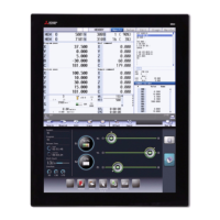
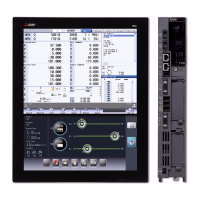
Detailed specifications and dimensions of the control unit.
Specifications and dimensions for the display units.
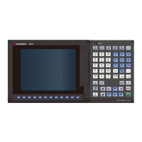
Specifications and dimensions for various keyboard units.
Characteristics of operation panel I/O units, including points and types.
Specifications for remote I/O units, including signal types and points.
Specifications for MITSUBISHI CNC machine operation panels.
Methods and considerations for managing heat radiation from installed units.
Measures and techniques to mitigate noise interference in the system.
Procedures for physically installing various system units.
Essential precautions to follow before and during wiring operations.
Detailed procedures for connecting various devices to the control unit.
Steps for connecting the operation panel I/O unit to other components.
Procedures for connecting remote I/O units to the system.
Connecting MITSUBISHI CNC machine operation panels.
Details on cable wire specifications and assembly methods.
Connection diagram for the CNP2E-1 cable.
Connection diagrams for CNP3EZ-2P/CNP3EZ-3P cables.
Connection diagram for F023/F024 cables.
Connection diagram for FCUA-R030 cable.
Connection diagrams for FCUA-R300/FCUA-R301 cables.
List of available cable connector sets and their package contents.
Key measures for achieving EMC compliance.
Measures related to panel structure for EMC.
Precautions and measures for wiring within the panel for EMC.
Specific parts and components used for EMC countermeasures.
Regulations and restrictions for packing lithium batteries for transportation.
Guidelines for users on handling lithium batteries during shipping.
Product information data sheet for ER batteries, including hazards and handling.
Guidance on selecting UL-approved external 24VDC power supply units.
Importance of maintaining unit ambient temperature within specified limits for UL compliance.