Do you have a question about the Mitsubishi Electric MELDAS FCU6-DX561 and is the answer not in the manual?
| Category | Control Systems |
|---|---|
| Type | Controller |
| Axis Control | Up to 6 axes |
| Communication Interface | RS-232 |
| Program Storage | Flash Memory |
| Operating Temperature | 0 to 50°C |
| Humidity | 20-80% (non-condensing) |
| Control System | CNC |
Manual overview, scope, and related documents.
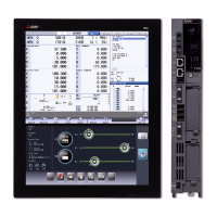
System configuration and architecture overview.
Detailed system configuration diagram showing interconnected units.
Guidelines and requirements for installing the unit.
Technical specifications for unit installation and operation.
Methods for reducing noise, including FG connection, shield clamping, and spark killers.
Physical installation guidelines, clearances, and orientation.
Specific environmental and mounting requirements for the unit.
Overall system connection overview and diagrams.
Diagram illustrating system component interconnections.
Detailed procedures for connecting various units and signals.
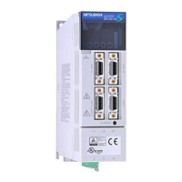
Identification of unit connectors and components.
Diagram showing how units are interconnected.
Specific steps for connecting the base I/O unit.
Procedures for connecting remote I/O (RIO) units.
Instructions for connecting the 24VDC power supply.
How to connect encoder signals for speed measurement.
Details for connecting machine input and output signals.
Guide for manufacturing the FCUA-R000 encoder cable.
Guide for manufacturing the FCUA-R211 communication cable.
Guide for manufacturing the FCUA-R220 power supply cable.
Guide for manufacturing the R300 DI/DO cable.
Guide for manufacturing the R301 DI/DO cable.
Instructions for manufacturing the R-TM terminator.
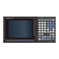
Overview of the module's functions and components.
Detailed explanation of the FX2N-80BMT-NC card functions.
Methods for diagnosing and resolving system faults.
Explanation of the unit's status indicator LEDs.
Comprehensive guide to troubleshooting system issues, including trouble confirmation and actions.
Procedures for routine maintenance and inspections.
List and description of tools required for maintenance.
Step-by-step instructions for replacing unit components like cables and the unit itself.