Do you have a question about the Mitsubishi Electric MELDAS M635 and is the answer not in the manual?
| Manufacturer | Mitsubishi Electric |
|---|---|
| Model | MELDAS M635 |
| Axis Control | 8 axes |
| Frequency | 50/60 Hz |
| Type | CNC |
| Interpolation | Linear, Circular |
| Communication | RS-232C, Ethernet |
| Display | LCD display |
| Power Supply | AC |
| Input Voltage | 200V - 240V |
| Minimum Command Increment | 0.001 mm |
| Positioning Resolution | 0.0001 mm |
| Operating Temperature | 0-45°C |
| Storage Temperature | -20-60°C |
| Humidity | Less than 80% (non-condensing) |
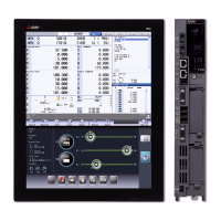
Overview of the system architecture and connected components.
Environmental and power specifications for unit installation.
Guidelines for operation box dimensions, depth, and heat radiation.
Methods for preventing and mitigating electrical noise.
Procedure for connecting the frame ground for noise reduction.
Techniques for effectively shielding cables to prevent noise.
Methods for protecting the system against lightning surges.
General installation procedures and considerations.
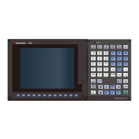
Specific instructions for installing the control unit with display.
Overall system wiring overview for M615/M635 and M610/M630.
System connection diagram specific to the M615/M635 series.
System connection diagram specific to the M610/M630 series.
Detailed instructions for connecting the control unit's interfaces.
Diagram showing the layout of connectors on the control unit.
Pin assignments for various control unit connectors.
Procedure for connecting a floppy disk drive to the control unit.
Instructions for inserting and connecting PCMCIA cards.
Steps for connecting a hard disk drive to the control unit.
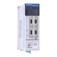
Guide to connecting power supply units.
Specific connection details for the PD25A power supply unit.
Instructions for connecting a general-purpose stabilized power supply.
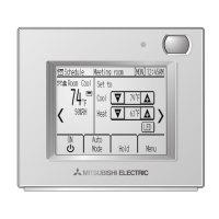
Wiring and connection diagrams for the operation board.
Connection diagram for M615/635 with 10.4" color STN.
Connection diagram for M610/630 with 10.4" monochrome STN.
Pin assignments for operation board connectors.
Wiring diagram for the emergency stop button connection.
Detailed connection system, layout, and pin assignments for Base I/O units.
Pin assignments for Base I/O unit connectors like CF10, SV1, SV2, ENC1.
Connecting servo amplifiers to the SV1 and SV2 ports of the Base I/O unit.
Connecting encoders to ENC1 on Base I/O and ENC2 on the control unit.
Details on using, specifying, and connecting card-sized I/O modules.
Information on Scan I/O types, connectors, and station settings.
Connection methods for Scan I/O, including power and remote I/O.
Power supply requirements and connection for remote I/O units.
Key measures for achieving EMC compliance, including grounding and shielding.
Best practices for wiring within panels to minimize noise propagation.
Detailed examples of grounding connections for the NC unit.
Proper shielding techniques for various cables to reduce noise.