Do you have a question about the Mitsubishi Electric MAC-333IF-E and is the answer not in the manual?
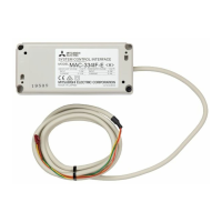
Lists power supply, dimensions, usage conditions, and cable specifications.
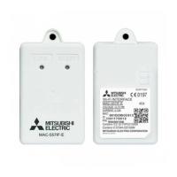
Provides physical dimensions and mounting hole details of the unit.
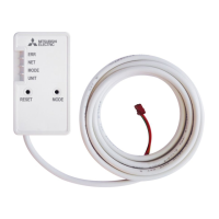
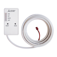
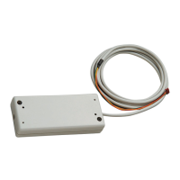
Instructions for connecting the unit to the indoor air conditioner.
Details on connecting the unit to various systems.
Steps for wiring the M-NET communication cable.
Instructions for connecting the MA remote controller.
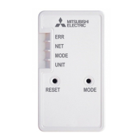
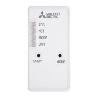
Explains how to check communication status using LED indicators.
Configuration of M-NET addresses using rotary switches.
Setting refrigerant addresses using a rotary switch.
Configuration of functions using Dip Switch SW500.
Configuration of functions using Dip Switch SW502.
Describes M-NET communication control for centralized/separate control.
Details on connecting the MA remote controller for operation.
Covers various remote control methods including card keys, coin timers, and switches.
Card key functionality to stop the air conditioner.
Card key functionality to enable/disable remote operation.
Coin timer function to start/stop the air conditioner.
Remote control using continuous switches for prioritized operation.
Remote control using instantaneous switches for ON/OFF & disable/enable.
Remote control for switching between HEAT/COOL modes.
Relay outputs for ON/OFF operation and normal/abnormal signals.
LED indications for ON/OFF operation and normal/abnormal signals.
Relay outputs for ON/OFF operation and heater control signals.
Relay outputs for ON/OFF and humidifier control signals.
Covers display differences, timer, manual operation, troubleshooting, and group operation.
| Brand | Mitsubishi Electric |
|---|---|
| Model | MAC-333IF-E |
| Category | Recording Equipment |
| Language | English |