MDS-E/EH Series Instruction Manual
1 Installation
11
IB-1501229-F
1.1.9 Installation of Servo Motor
Mount the servo motor on a flange which has the following size or produces an equivalent or higher heat dissipation
effect:
(Note 1) These flange sizes are recommended dimensions when the flange material is an aluminum.
(Note 2) If enough flange size cannot be ensured, ensure the cooling performance by a cooling fan or operate the
motor in the state that the motor overheat alarm does not occur.
1.1.10 Cable Stress
[1] Sufficiently consider the cable clamping method so that bending stress and the stress from the cable's own weight
is not applied on the cable connection part.
[2] In applications where the servo motor moves, make sure that excessive stress is not applied on the cable.
If the encoder cable and servo motor wiring are stored in a cable bear and the servo motor moves, make sure that
the cable bending part is within the range of the optional encoder cable.
Fix the encoder cable and power cable enclosed with the servo motor.
[3] Make sure that the cable sheathes will not be cut by sharp cutting chips, worn or stepped on by workers or vehicles.
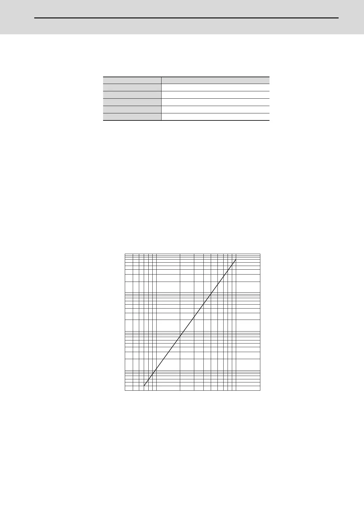
The bending life of the encoder cable is as shown below. Regard this with a slight allowance. If the servo motor/spindle
motor is installed on a machine that moves, make the bending radius as large as possible.
Flange size (mm) Servo motor capacity
150×150×6 100W
250×250×6 200 to 400W
250×250×12 0.5 to 1.5kW
300×300×20 2.0 to 7.0kW
800×800×35 9.0 to 11.0kW
Encoder cable bending life
(Material of Mitsubishi optional encoder cable: A14B2343)
(Note) The values in this graph are calculated values and are not guaranteed.
4 7 10 20 40 70 100 200
1× 10
8
5× 10
7
2× 10
7
1× 10
7
5× 10
6
2× 10
6
1× 10
6
5× 10
5
2× 10
5
1× 10
5
5× 10
4
3× 10
4
Bending radius (mm)
No. of bends (times)
4 7 10 20 40 70 100 200
3 x 10
4
5 x 10
4
1 x 10
5
2 x 10
5
5 x 10
5
1 x 10
6
2 x 10
6
5 x 10
6
1 x 10
7
2 x 10
7
5 x 10
7
1 x 10
8
 Loading...