B
Benjamin TaylorAug 5, 2025
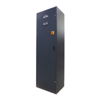
Why is there high pressure at the delivery in my Mitsubishi Electric MEGR Air Conditioner?
- TThomas ChenAug 6, 2025
High pressure at the delivery can be caused by several factors related to the remote condenser or the refrigerant circuit. For the remote condenser, check if the fan is turning freely, the power supply to the fan, the condensation controller signal, if the condensing coil is clean, for recirculation of hot air, and the remote condenser sizing. Regarding the refrigerant circuit, verify the refrigerant charge, check for incondensable substances, and inspect the refrigerant circuit's taps.