Do you have a question about the Mitsubishi Electric MR-C405C-W-A and is the answer not in the manual?
| Brand | Mitsubishi Electric |
|---|---|
| Model | MR-C405C-W-A |
| Category | Refrigerator |
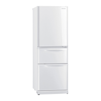
| Color | White |
| Adjustable Shelves | Yes |
| Door Bins | Yes |
| Ice Maker | No |
| Voltage | 220-240V |
| Frequency | 50 Hz |
| Total Capacity | 405L |
| Shelves Material | Glass |
Detailed specifications for refrigerator models, including power, capacity, dimensions, insulation, cooling system, and components.
Electrical specifications for key components like compressor, fan motors, heaters, and thermistors.
Detailed wiring diagram showing component connections and color codes for refrigerator models.
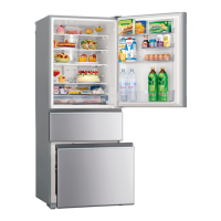
Illustrates and labels the various shelves, pockets, and trays within the refrigerator compartment.
Details the components of the automatic ice-making system, including tank, pump, and filter.
Identifies parts within the freezer compartment, such as ice cases and containers.
Labels the sliding case and vegetable cases within the vegetable compartment.
Provides check methods and criteria for diagnosing main components like compressors, motors, and capacitors.
Explains the operation panel functions, including normal operation and ice making test/self-check procedures.
Outlines the self-check troubleshooting process, including LED indicators and error detection.
Illustrates test points on the main control board and lists connector pin assignments for diagnostics.
Steps for detaching control PCB, compressor cover, and elect cover, including screw counts.
Procedures for detaching vegetable compartment parts, including cases and water pump.
Steps for gas collection, pipe detachment, and compressor/dryer replacement.
Diagram and list of door and body parts for refrigerator models.
Diagram and list of electrical components, including thermistors, lamps, and motors.
Diagram and list of accessory parts such as shelves, ice boxes, and trays.
Illustration and list of packing materials for shipping.