EasyManua.ls Logo

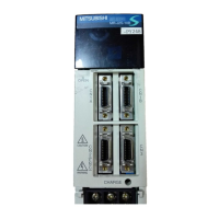
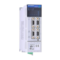
Mitsubishi Electric MR-J2S-10B User Manual

Mitsubishi Electric MR-J2S-10B
225 pages
To Next Page IconTo Next Page
Page #1 background imageLoading...
Page #1 background image
General-Purpose AC Servo
MODEL
MR-J2S- B
SERVO AMPLIFIER
INSTRUCTION MANUAL
SSCNET Compatible
J2-Super Series
F

Table of Contents

Other manuals for Mitsubishi Electric MR-J2S-10B

Questions and Answers:

Mitsubishi Electric MR-J2S-10B Specifications

General IconGeneral
TypeServo Amplifier
ModelMR-J2S-10B
SeriesMR-J2S
Rated Output100 W
Output Power100 W
Voltage200 V
Control ModePosition, Speed, Torque
Protection FunctionsOvercurrent, Overvoltage
Ambient Temperature0°C to 55°C
Ambient HumidityLess than 90% (non-condensing)
Vibration Resistance5.9 m/s²

Summary

Safety Instructions

FUNCTIONS AND CONFIGURATION

INSTALLATION

SIGNALS AND WIRING

Connection example of control signal system

Shows typical wiring diagrams for connecting control signals and multiple axes.

Alarm occurrence timing chart

Illustrates the sequence of events when an alarm occurs and how to reset it.

Connection of servo amplifier and servo motor

Provides wiring diagrams for connecting the servo amplifier to the servo motor, including grounding.

Servo motor with electromagnetic brake

Explains the configuration and operation of the electromagnetic brake circuit for safety.

Grounding

Emphasizes the importance of proper grounding for safety and noise reduction.

OPERATION AND DISPLAY

When switching power on for the first time

Checks to perform before initial power-on for correct operation and safety.

Start up procedures and parameter setting

Guides on initial power-on steps, servo-on, home position return, and parameter configuration.

Servo amplifier display and indications

Explains the servo amplifier display sequence and lists various indications for status and troubleshooting.

Test operation mode

Explains manual jog, positioning, program, and motorless operations using MR Configurator.

PARAMETERS

GENERAL GAIN ADJUSTMENT

Different adjustment methods

Details gain adjustment methods using auto tuning modes (1 & 2) and manual modes.

Adjustment using MR Configurator

Explains gain adjustments via machine analyzer, gain search, and machine simulation using software.

Auto tuning mode operation

Illustrates auto tuning process, including estimation and automatic parameter setting.

Adjustment procedure by auto tuning

Provides a step-by-step guide for adjusting servo gains using the auto tuning feature.

Manual mode 1: Operation and adjustment

Details manual adjustment of key gains (PG1, VG2, VIC) for fine-tuning.

SPECIAL ADJUSTMENT FUNCTIONS

Machine resonance suppression filter: Function and Parameters

Details setting notch frequency and depth to suppress machine resonance.

Adaptive vibration suppression control: Function and Parameters

Explains automatic detection and suppression of mechanical system vibration.

Gain changing function: Applications, Block Diagram, and Parameters

Covers gain changing applications, block diagram, parameters, and operation examples.

INSPECTION

TROUBLESHOOTING

Alarms and warning list

Lists alarms and warnings with display codes, names, and deactivation methods.

Remedies for alarms

Provides causes and actions for rectifying servo amplifier alarms.

Remedies for warnings

Lists causes and actions for resolving servo amplifier warnings.

OUTLINE DIMENSION DRAWINGS

CHARACTERISTICS

Overload protection characteristics

Illustrates how the servo amplifier protects against overload conditions through thermal relays.

Dynamic brake characteristics

Details the operation of the dynamic brake and formulas for calculating stopping distance.

OPTIONS AND AUXILIARY EQUIPMENT

ABSOLUTE POSITION DETECTION SYSTEM

Related product manuals