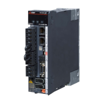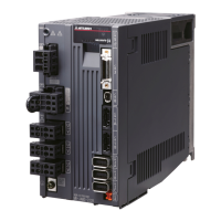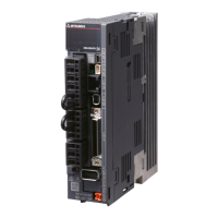
Do you have a question about the Mitsubishi Electric MR-J5 Series and is the answer not in the manual?
| Series | MR-J5 |
|---|---|
| Type | Servo Drives |
| Manufacturer | Mitsubishi Electric |
| Position Control | Yes |
| Speed Control | Yes |
| Torque Control | Yes |
| Advanced One-touch Tuning | Yes |
| Real-time Autotuning | Yes |
| Vibration Suppression Control | Yes |
| Protection Class | IP20 |
| Input Power Supply | Single-phase or Three-phase AC |
| Feedback System | Absolute/Incremental Encoder, Resolver |
| Communication Interface | CC-Link IE TSN |
| Safety Function | STO (Safe Torque Off) |
| Protection Functions | Overvoltage, undervoltage, overload, overheat |
| Ambient Temperature | 0 to 55°C |
| Storage Temperature | -20 °C to +65 °C |
| Ambient Humidity | Up to 90% (non-condensing) |
| Vibration Resistance | 5.9 m/s² (0.6 G) in X, Y, and Z directions |
| Installation | Panel mounting |
| Weight | Varies by model |
| Control Method | Sine-wave PWM, Current control system |
Indicates that incorrect handling may cause hazardous conditions, resulting in death or severe injury.
Indicates that incorrect handling may cause hazardous conditions, resulting in medium or slight injury.
Symbols indicating what must not be done and what must be done.
Warnings related to electrical shock prevention during installation and wiring.
Warnings related to electrical shock prevention during setting and adjustment.
Warnings related to electrical shock prevention during operation.
Warnings related to electrical shock prevention during maintenance.
This section covers the manual's scope and provides abbreviations for servo amplifiers.
Table for converting SI units to U.S. customary units for necessary values.
Step-by-step guide for wiring the servo amplifier and related components.
Procedures and checks for correct wiring of the servo amplifier and motor.
Guidelines for handling cables and ensuring a suitable environment for operation.
Specifications for mounting direction and required clearances for installation.
Precautions to prevent foreign materials from entering the servo amplifier.
Guidelines for managing cable stress to prevent damage and ensure reliability.
Steps for replacing the fan unit of the servo amplifier.
Conditions and restrictions for using the product at high altitudes.
Wiring diagrams and examples for power circuit connections.
Examples of I/O signal connections for different models and interface types.
Detailed explanation of power supply systems and terminal connections.
Pin assignments for various connectors on the servo amplifier.
Detailed explanation of input and output signals and their functions.
Internal connection diagrams for different models and interface types.
Mechanical dimensions for 200 V class servo amplifiers.
Technical specifications and diagrams for various connectors.
Detailed specifications and diagrams for the CN3 connector (Model A).
Detailed specifications and diagrams for the CN3 connector (Model WG).
Graphs showing overload protection characteristics for different models.
Tables indicating power supply capacities and generated heat for various models.
Information and graphs on dynamic brake characteristics and time constants.
Graph showing cable bending life based on bend radius.
Data on inrush currents during power-on for main and control circuits.
Lists and descriptions of available cable and connector sets.
Details on combinations with regenerative options and their power values.
Information on the MR-CM simple converter and its specifications.
Details on the PS7DW-20V14B-F junction terminal block and its connection example.
Details on the MR-TB50 junction terminal block and its terminal assignments.
Details on the MR-TB26A junction terminal block and its specifications.
Information about the MR Configurator2 engineering tool and precautions.
Guidance on selecting appropriate wire sizes and crimp terminals.
Recommended circuit breakers, fuses, and magnetic contactors for power supply.
Information on the advantages, dimensions, and installation of DC reactors.
Information on the advantages, dimensions, and installation of AC reactors.
Recommended relay types for different interfaces.
Techniques and products for reducing noise in the system.
Guidance on selecting earth-leakage current breakers based on calculated values.
Recommendations for EMC filters to comply with EN EMC directive.
Overview of the absolute position detection system, its characteristics, and restrictions.
Information on battery-less and battery backup encoder connections and specifications.
Standard connection example and signal explanation for absolute position detection using DIO.
Cautions and outline of the STO function, including safety standards and terms.
Pin assignments and signal explanations for the STO I/O connector.
Connection examples for the STO function using external safety relay units.
Details on sink and source I/O interfaces, including digital input/output.
Comparison of linear and rotary servo motors, and configuration details.
Startup procedures for linear servo motors with specific parameters.
Startup procedures for linear servo motors with specific parameters.
Explanation of homing operations and linear encoder settings.
Details on auto tuning and machine analyzer functions.
Overload protection characteristics for different linear servo motor series.
Operating conditions and requirements for absolute position detection systems.
Comparison of direct drive motors and rotary servo motors, and configuration.
Startup procedures for direct drive motors with specific parameters.
Startup procedures for direct drive motors with specific parameters.
Explanation of servo control error detection functions for direct drive motors.
Overload protection characteristics for direct drive motors.
Precautions and requirements for absolute position detection systems.
Precautions and requirements for absolute position detection systems with DIO.
Information on battery selection, combination, and replacement procedures.
Details on manual revision history and publication dates.
Details on warranty terms, limitations, and exclusions.
Information regarding repair availability after product discontinuation.
Information on service availability and procedures in overseas locations.
Limitations on warranty liability for indirect damages.
Disclaimer regarding changes in product specifications.
Guidelines and restrictions on product application and usage.
List of registered trademarks and product names.


