Do you have a question about the Mitsubishi Electric Mr.Slim MU-A30ND-S1 and is the answer not in the manual?
| Series | Mr. Slim |
|---|---|
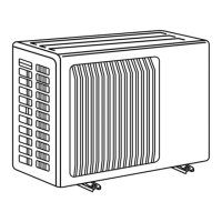
| Model | MU-A30ND-S1 |
| Power Supply | 220-240 V, 50 Hz |
| Refrigerant | R410A |
| Weight (Indoor Unit) | 9 kg |
| Outdoor Unit Dimensions (W x H x D) | 780 x 540 x 269 mm |
Details maximum refrigerant piping length and height difference for different models.
Specifies additional refrigerant charge based on piping length for different models.
Shows outdoor low pressure and current based on ambient temperature and humidity.
Provides essential safety precautions and general advice before starting troubleshooting.
Outlines a step-by-step process to diagnose and resolve issues based on indicator lamp patterns.
Lists key components and their resistance/voltage criteria for diagnosing faults.
Flowchart guiding diagnosis when compressor or fan motor fails to operate.
Flowchart for diagnosing issues when compressor or fan motor fails to stop.
Instructions to identify and rectify incorrect wiring connections causing operational issues.
Procedure to test the expansion valve for proper operation and diagnose related faults.
Method to test thermistors in the outdoor unit for abnormalities causing operational issues.
Steps to diagnose solenoid valve coil issues when the unit repeatedly starts and stops.
Explains the operational logic of the solenoid valve based on thermistor readings.
Illustrates test points and voltage values on the deicer P.C. board for diagnosis.
Step-by-step guide to remove the outer cabinet of the MU-A18ND outdoor unit.
Instructions for removing electrical components like capacitors and terminal blocks.
Steps to safely detach and remove the outdoor fan motor assembly.
Procedure for safely recovering refrigerant and removing the compressor unit.
Detailed steps for disassembling the outer cabinet of the MU-A24ND outdoor unit.
Guide for removing electrical components such as capacitors and contactors from MU-A24ND.
Instructions for detaching the propeller and the outdoor fan motor.
Steps for safely removing the compressor after refrigerant recovery and pipe disconnection.
Step-by-step guide to remove the outer cabinet of the MU-A30ND outdoor unit.
Instructions for safely disconnecting and removing the deicer printed circuit board.
Steps to detach the propeller and the outdoor fan motor.
Procedure for safely removing the compressor unit.
Lists structural, electrical, and functional parts for the MU-A18ND outdoor unit with part numbers.
Lists structural, electrical, and functional parts for MU-A24ND and MU-A30ND outdoor units.
Lists RoHS compliant parts for the MU-A18ND outdoor unit.
Lists RoHS compliant parts for MU-A24ND and MU-A30ND outdoor units.