EasyManua.ls Logo

Mitsubishi Electric Mr.Slim MUZ-GC25NA - C1 User Manual

Mitsubishi Electric Mr.Slim MUZ-GC25NA - C1
64 pages
To Next Page IconTo Next Page
Page #1 background imageLoading...
Page #1 background image
SERVICE MANUAL
CONTENTS
1. PART NAMES AND FUNCTIONS· ···················· 3
2. SPECIFICATION ················································ 4
3. OUTLINES AND DIMENSIONS ························ 8
4. WIRING DIAGRAM ············································ 9
5. REFRIGERANT SYSTEM DIAGRAM ············· 14
6. PERFORMANCE CURVES ····························· 18
7. ACTUATOR CONTROL ··································· 23
8. SERVICE FUNCTIONS ··································· 24
9. TROUBLESHOOTING ····································· 24
10. DISASSEMBLY INSTRUCTIONS ···················· 54
Models
SPLIT-TYPE AIR CONDITIONERS
MUZ-GC25NA -
C1
MUZ-GC35NA -
C1
MUZ-GC35NA -
C2
MUZ-GC50NA -
C1
MUZ-GC50NA -
C2
MUZ-GC60NA -
C1
MUZ-GC60NA -
C2
MUZ-GC71NA -
C1
NOTE:
RoHS compliant products have <G> mark on the spec name plate.
HFC
utilized
R410A
No. OBH482
REVISED EDITION-C
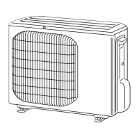
OUTDOOR UNIT
Indoor unit service manual
MSZ-GC•NA Series (OBH481)
MUZ-GC25/35NA
PARTS CATALOG (OBB482)
Please void OBH482 REVISED EDITION-B.
Revision C:
MUZ-GC35NA -
C2
has been added.

Table of Contents

Question and Answer IconNeed help?

Do you have a question about the Mitsubishi Electric Mr.Slim MUZ-GC25NA - C1 and is the answer not in the manual?

Mitsubishi Electric Mr.Slim MUZ-GC25NA - C1 Specifications

General IconGeneral
BrandMitsubishi Electric
ModelMr.Slim MUZ-GC25NA - C1
CategoryAir Conditioner
LanguageEnglish

Summary

1. PART NAMES AND FUNCTIONS

2. SPECIFICATION

3. OUTLINES AND DIMENSIONS

4. WIRING DIAGRAM

5. REFRIGERANT SYSTEM DIAGRAM

MAX. REFRIGERANT PIPING LENGTH and MAX. HEIGHT DIFFERENCE

ADDITIONAL REFRIGERANT CHARGE (R410A : g)

6 PERFORMANCE CURVES

6-1. CAPACITY AND INPUT CURVES

Shows cooling capacity and input power based on temperature and humidity.

6-2. CAPACITY AND INPUT CORRECTION BY OPERATIONAL FREQUENCY OF COMPRESSOR

Provides correction factors for capacity and input based on compressor frequency.

6-3. TEST RUN OPERATION

Explains the procedure for fixed-frequency test operation.

6-4. OUTDOOR LOW PRESSURE AND OUTDOOR UNIT CURRENT

Graphs outdoor low pressure and unit current versus ambient conditions.

7 ACTUATOR CONTROL

7-1. OUTDOOR FAN MOTOR CONTROL

Details the ON/OFF timing for the outdoor fan motor.

7-2. R.V. COIL CONTROL

Explains the operation of the reversing valve coil in different modes.

7-3. RELATION BETWEEN MAIN SENSOR AND ACTUATOR

Maps sensors to their corresponding actuators and operational purposes.

8 SERVICE FUNCTIONS

8-1. CHANGE IN DEFROST SETTING

Describes how to modify the defrost finish temperature setting.

8-2. PRE-HEAT CONTROL SETTING

Explains the activation and purpose of the pre-heat control.

9 TROUBLESHOOTING

9-1. CAUTIONS ON TROUBLESHOOTING

Lists important precautions to observe before and during troubleshooting.

9-2. FAILURE MODE RECALL FUNCTION

Details how to recall and interpret stored failure codes.

3. Outdoor unit failure mode table

Lists outdoor unit failure modes, LED indications, conditions, and correspondences.

9-3. TROUBLESHOOTING CHECK TABLE

Correlates symptoms, LED indications, and potential causes for MUZ-GC25/35NA.

9-4. TROUBLE CRITERION OF MAIN PARTS

Specifies resistance and voltage criteria for checking key components.

9-5. TROUBLESHOOTING FLOW

Step-by-step diagnostic procedures for various unit malfunctions.

9-6. TEST POINT DIAGRAM AND VOLTAGE

Illustrates test points and voltage/resistance measurements on P.C. boards.

Electromagnetic noise enters into TV sets or radios

Related product manuals