Do you have a question about the Mitsubishi Electric Mr.Slim MUZ-GC50NA - C1 and is the answer not in the manual?
| Brand | Mitsubishi Electric |
|---|---|
| Model | Mr.Slim MUZ-GC50NA - C1 |
| Category | Air Conditioner |
| Language | English |
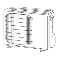
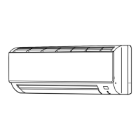
Diagrams labeling parts for different models.
Detailed electrical specs, capacity, and performance metrics.
Ratings and specifications for key electrical components.
Diagrams showing physical dimensions and required clearance for installation.
Electrical wiring diagram for specific outdoor unit models.
Electrical wiring diagram for specific outdoor unit models.
Diagram illustrating the refrigerant circuit for specific models.
Diagram illustrating the refrigerant circuit for specific models.
Diagram illustrating the refrigerant circuit for specific models.
Diagram illustrating the refrigerant circuit for specific models.
Table outlining maximum refrigerant piping limits and height differences.
Guidelines for calculating extra refrigerant charge based on piping length.
Graphs showing cooling capacity and total input at rated frequency.
Charts showing capacity and input correction based on compressor frequency.
Instructions for performing a fixed-frequency test run operation.
Graphs showing outdoor low pressure and unit current under cooling operation.
Description of how the outdoor fan motor operates in relation to the compressor.
Explanation of the 4-way valve operation during cooling and heating modes.
Table mapping sensors to actuators for different model groups.
Procedure for changing the defrost finish temperature setting.
Method for activating pre-heat control to prevent compressor issues.
Safety guidelines and initial checks before troubleshooting.
Step-by-step guide to recall stored failure information.
Detailed flowchart for recalling outdoor unit specific failure modes.
Table mapping LED indications to failure modes and correspondences.
Table mapping LED indications to failure modes and correspondences.
Table mapping LED indications to failure modes and correspondences.
Table correlating symptoms, LED indications, and troubleshooting steps.
Table correlating symptoms, LED indications, and troubleshooting steps.
Table correlating symptoms, LED indications, and troubleshooting steps.
Table correlating symptoms, LED indications, and troubleshooting steps.
Resistance and voltage checks for key components.
Resistance and voltage checks for key components.
Flowcharts to diagnose inverter and compressor issues.
Steps to check for open phase and compressor health.
Procedures for checking compressor winding resistance and operation time.
Analyzing compressor stop times due to overcurrent for diagnosis.
Steps to identify and address compressor start failure.
Procedure to measure resistance of outdoor thermistors for fault diagnosis.
Checks for R.V. coil operation in cooling and heating modes.
Diagnosing R.V. coil and 4-way valve problems during heating.
Diagnosing R.V. coil and 4-way valve problems during cooling.
Procedures to test fan motor resistance and voltage supply.
Checking input voltages to various boards and units.
Verifying voltages on inverter and indoor electronic control boards.
Testing LEV operation, vibration, and coil resistance.
Measuring voltage at the LEV connector for proper operation.
Checking the fuse and LED status on the inverter P.C. board.
Checking power supply, wiring integrity, and serial signal status.
Verifying power and serial signal for specific models.
Testing HPS resistance and verifying protection activation.
Steps to diagnose and mitigate electromagnetic noise affecting TVs/radios.
Diagram showing test points and voltage locations on the inverter board.
Diagram showing test points and voltage locations on the inverter board.
Diagram showing test points for thermistors and signals on the control board.
Diagram showing component layout and connections on the noise filter board.
Diagram showing connections and test points on the outdoor power board.
Explanation of how to detach terminals with locking mechanisms.
Step-by-step guide for removing outer panels and cabinets.
Steps for removing the inverter assembly and related P.C. boards.
Procedure for removing the Reversing Valve coil.
Steps for removing discharge and defrost thermistors.
Instructions for removing the outdoor fan motor assembly.
Steps for removing the compressor and the 4-way valve.
Detailed steps for disassembling cabinets and panels for specific models.
Procedures for removing inverter and power board assemblies.
Steps for removing the inverter assembly for a specific model.
Instructions for removing R.V. coil and various thermistors.
Steps for disconnecting and removing the outdoor fan motor.
Steps for detaching pipes and removing the compressor and 4-way valve.
Instructions for removing the reactor component.