SERVICE MANUAL
CONTENTS
1. REFERENCE MANUAL
........................
2
2. SAFETY PRECAUTION
........................
3
3. PARTS NAMES AND FUNCTIONS
......
5
4. SPECIFICATIONS
...............................
11
5. NOISE CRITERION CURVES
.............
13
6. OUTLINES AND DIMENSIONS
............
15
7. WIRING DIAGRAM
.............................
16
8.
REFRIGERANT SYSTEM DIAGRAM
......
17
9. TROUBLESHOOTING
........................
18
10. FUNCTION SETTING
.........................
32
11. SPECIAL FUNCTION
..........................
33
12. DISASSEMBLY PROCEDURE
...........
37
PARTS CATALOG (OCB640)
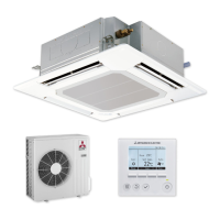
WIRED REMOTE
CONTROLLER
(Option)
IR WIRELESS REMOTE
CONTROLLER
(Option)
ON/OFF TEMP
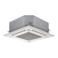
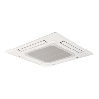
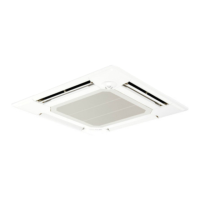
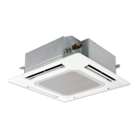
INDOOR UNIT
Model name
indication for
MAIN UNIT
Model name
indication for GRILLE
PLA-A12EA7
PLA-A18EA7
PLA-A24EA7
PLA-A30EA7
PLA-A36EA7
PLA-A42EA7
PLA-A12EA7
PLA-A18EA7
PLA-A24EA7
PLA-A30EA7
PLA-A36EA7
PLA-A42EA7
Indoor unit
[Model Name] [Service Ref.]
SPLIT-SYSTEM HEAT PUMP
No. OCH640
REVISED EDITION-C
September 2018
Revision:
• WIRING DIAGRAM has
been modified in REVISED
EDITION-C.
•
Some descriptions have
been modified.
OCH640 REVISED EDITION-B
is void.