Do you have a question about the Mitsubishi Electric Mr.Slim PUHZ-RP35VHA3 and is the answer not in the manual?
| Brand | Mitsubishi Electric |
|---|---|
| Model | Mr.Slim PUHZ-RP35VHA3 |
| Category | Air Conditioner |
| Language | English |
Lists service manuals for various indoor units, including model names and service manual numbers.
Refers to a technical data book with manual number OCS05.
General safety reminder to disconnect all supply circuits before accessing terminals.
Critical cautions for using refrigerant R410A, covering pipe prep, tools, and handling.
Lists exclusive service tools required for R410A refrigerant, with specifications.
Explains unit's ability to detect leakage and initial learning requirements.
Precautions for reusing R22 pipes with new units, including flowchart.
Details R410A piping work cautions, pipe thickness, flare dimensions, and tool usage.
Pre-charged refrigerant system for simplified installation and improved reliability.
Describes unit's capability to detect refrigerant leakage over time.
Table showing refrigerant charge amounts (kg) based on piping length for various models.
Provides technical data for compressors, including model names and winding resistance.
Noise curves showing sound pressure levels across frequencies for various unit models.
Tables detailing standard operation data for indoor/outdoor units, including capacity, pressures, and temperatures.
Instructions for securing the unit firmly with foundation bolts (M10).
States piping and wiring connections can only be made from the rear direction.
Guidance on attaching the conduit by fixing a metal plate to the back panel.
Diagrams and specifications for required minimum installation space around the outdoor unit.
Lists symbols and names related to the M-NET adapter, including terminal blocks, connectors, and switches.
Details power wiring specs, including voltage, capacity, wire size, and rating for various models.
Illustrates wiring for a 1:1 system, showing connections between indoor, outdoor units, and remote controller.
Illustrates wiring for synchronized twin/triple systems, detailing connections.
Explains connection patterns for separate power supplies, including diagrams and DIP switch settings.
Specifies requirements for indoor-outdoor cables, including wire size, length, and connection methods.
Details M-NET wiring, including precautions for noise and grounding.
Summary of unit conditions, error codes, and service actions for recurring/non-recurring issues.
Points to check before test run, including installation, wiring, and safety.
Steps to interpret and clear error codes displayed on the remote controller during operation.
Steps to recall and check error code history for each unit using the remote controller.
Procedure to diagnose the remote controller if the air conditioner cannot be operated from it.
Method for diagnosing malfunctions using the wireless remote controller, including procedures and error indicators.
Lists errors detected by the indoor unit, their check codes, symptoms, and remarks.
Lists errors detected by outdoor units or other components, including check codes, symptoms, and remarks.
Table detailing abnormalities detected at power-on, their causes, and service actions.
Lists various error codes and the conditions under which they occur during unit operation.
Lists common phenomena, factors, and countermeasures for troubleshooting.
How to set unit functions using the remote controller, referencing tables for available functions.
Provides meanings for different indoor temperature detection settings (ta=A, B, C).
Flowchart and instructions for selecting functions using the wired remote controller, including setting language and mode.
Instructions for selecting functions using the wireless remote controller, detailing steps for setting unit number, mode, and setting number.
Details remote controller function settings like language, limit, mode, and display.
Step-by-step guide to access and view operation data using the remote controller's maintenance monitor.
Comprehensive list of request codes for monitoring operation data, including units and remarks.
Instructions on how to enter and operate maintenance mode using the remote controller.
Details how to activate maintenance mode, whether the unit is operated or stopped.
Explains how to fix operating frequency for inverter models to stabilize operation.
Steps for measuring and displaying operation data (e.g., refrigerant address, temperature) during stabilized operation.
Explains how refrigerant addresses are set for single and multi-refrigerant systems.
Guide to check operation conditions by comparing temperature differences against graphs.
Steps to select leakage detection mode and start initial learning for accurate detection.
Steps to start leakage judgment mode and interpret results, including cautions.
Step-by-step instructions with photos for removing the top, service, front, and back panels.
Instructions with photos for removing the fan motor, propeller, connector, and screws.
Detailed steps with photos for removing the electrical parts box and its connectors.
Instructions with photos for removing outdoor thermistors TH6, TH3, and TH33.
Instructions with photos for removing the outdoor thermistor TH7, noting it's combined with TH6.
Instructions with photos for removing thermistors TH3, TH33, and TH4.
Steps with photos for removing the 4-way valve coil, LEV coils, and bypass valve coil.
Instructions with photos for removing the 4-way valve, including valve bed and refrigerant recovery.
Instructions with photos for removing the LEV, including refrigerant recovery and welded parts.
Steps with photos for removing the bypass valve coil and bypass valve, including refrigerant recovery.
Instructions with photos for removing the high pressure switch, including refrigerant recovery.
Steps with photos for removing the reactor (DCL) and capacitor (CE).
Detailed steps with photos for removing the compressor, including separator, fixing nuts, and welded pipes.
Instructions with photos for removing the power receiver, including welded pipes and receiver legs.
Steps with photos for disassembling the electrical parts box, including disconnecting connectors and removing plates.
Instructions with photos for removing the reactors (ACL1, ACL2, ACL3) and their boxes.
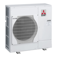
Lists structural parts for PUHZ-RP35/50VHA2 models, including part numbers, names, specifications, and quantities.
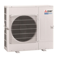
Lists structural parts for PUHZ-RP60/71VHA2 models, including part numbers, names, specifications, and quantities.
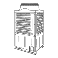
Lists structural parts for PUHZ-RP100/125/140VHA2 and YHA2 models, including part numbers and quantities.
Illustrated list of functional and electrical parts for PUHZ-RP35/50VHA2 models, with numbered components.
Illustrated list of functional and electrical parts for PUHZ-RP60/71VHA2 models, with numbered components.
Illustrated list of functional and electrical parts for PUHZ-RP100/125/140VHA2 models, with numbered components.
Illustrated list of functional and electrical parts for PUHZ-RP100/125/140YHA2 and YHA3 models, with numbered components.
Illustrated list of functional and electrical parts for PUHZ-RP35/50VHA2/VHA21/VHA3 models, with numbered components.
Illustrated list of functional and electrical parts for PUHZ-RP60/71VHA2/VHA21/VHA3 models, with numbered components.
Illustrated list of functional and electrical parts for PUHZ-RP100/125/140YHA2 and YHA3 models, with numbered components.