EasyManua.ls Logo

Mitsubishi Electric MS-07NV -E1 (WH) User Manual

Mitsubishi Electric MS-07NV -E1 (WH)
64 pages
To Next Page IconTo Next Page
Page #1 background imageLoading...
Page #1 background image
SERVICE MANUAL
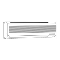
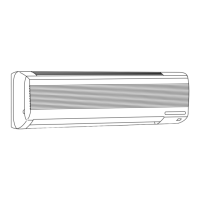
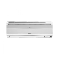
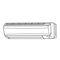
SPLIT-TYPE,HEAT PUMP AIR CONDITIONERS
CONTENTS
1. TECHNICAL CHANGES ····································2
2. PART NAMES AND FUNCTIONS······················3
3. SPECIFICATION·················································6
4. OUTLINES AND DIMENSIONS ·························9
5. WIRING DIAGRAM ··········································12
6. REFRIGERANT SYSTEM DIAGRAM··············20
7. PERFORMANCE CURVES······························24
8. MICROPROCESSOR CONTROL ····················27
9. SERVICE FUNCTIONS ····································34
10. TROUBLESHOOTING······································37
11. DISASSEMBLY INSTRUCTIONS·····················45
12. PARTS LIST······················································53
13. OPTIONAL PARTS···········································61
Wireless type
Models
MS-07NV -
(
WH
)
· MU-07NV -
MS-09NV -
(
WH
)
· MU-09NV -
MS-12NV -
(
WH
)
· MU-12NV -
MS-18NV -
(
WH
)
· MU-18NV -
MS-24NV -
(
WH
)
· MU-24NV -
MS-07NV -
(
WH
)
· MU-07NV -
MS-09NV -
(
WH
)
· MU-09NV -
MS-12NV -
(
WH
)
· MU-12NV -
MS-18NV -
(
WH
)
· MU-18NV -
MS-24NV -
(
WH
)
· MU-24NV -
MS-18NV -
(
WH
)
· MU-18NV -
E3E3
E2E2
E2E2
E2E2
E2E2
E2E2
E1E1
E1E1
E1E1
E1E1
E1E1
No. OB206
MS-18NV -
MS-24NV -
MS-18NV -
MS-24NV -
MS-18NV -
E3
E2
E2
E1
E1
This Servise Manual OB206 deals with MS-07/09/12/18/24NV-E1,
MU-07/09/12/18/24NV-E1, MS-18NV-E2, and MU-18NV-E2 in
OB175 THIRD EDITION issued in June in 1997.
Therfore, please refer to OB206, not to OB175 THIRD EDITION,
for the above models.
OB206t-1.qxp 25/9/97 6:42 PM Page 1

Questions and Answers:

Mitsubishi Electric MS-07NV -E1 (WH) Specifications

General IconGeneral
BrandMitsubishi Electric
ModelMS-07NV -E1 (WH)
CategoryAir Conditioner
LanguageEnglish

Summary

1 TECHNICAL CHANGES

2 PART NAMES AND FUNCTIONS

Indoor Unit Components

Identifies and describes parts of the indoor unit.

Outdoor Unit Components

Identifies and describes parts of the outdoor unit.

REMOTE CONTROLLER

3 SPECIFICATION

4 OUTLINES AND DIMENSIONS

5 WIRING DIAGRAM

Indoor Unit Wiring Diagram

Details the wiring diagram for the indoor unit.

Outdoor Unit Wiring Diagram

Details the wiring diagram for the outdoor unit.

6 REFRIGERANT SYSTEM DIAGRAM

Indoor Unit Refrigerant System

Illustrates the refrigerant system for the indoor unit.

Outdoor Unit Refrigerant System

Illustrates the refrigerant system for the outdoor unit.

EVACUATION PROCEDURES(AIR PURGE)

7 PERFORMANCE CURVES

Performance Curve Parameters

Lists key parameters like voltage, airflow, and main readings.

Measuring Temperature Difference

Provides steps to measure indoor air wet-bulb temperature difference.

8 MICROPROCESSOR CONTROL

Remote Control and Display Operation

Explains remote controller interaction and indoor unit display functions.

8. TIMER OPERATION

Timer Setting, Cancellation, and Programming

Provides instructions for setting, cancelling, and programming timers.

9. EMERGENCY-TEST OPERATION

Service Functions Overview

Details timer short mode and PC board modification for individual operation.

2. AUTO RESTART FUNCTION

10 TROUBLESHOOTING

Troubleshooting Cautions and Procedures

Lists precautions, servicing tips, and battery replacement for troubleshooting.

Troubleshooting Instructions and Check Tables

Provides troubleshooting flowcharts and a symptom check table.

Main Parts Trouble Criteria

Details diagnostic criteria and resistance checks for major components.

Component Diagnostic Checks (A-D)

Steps to diagnose various components like fan motor, receiver, PC boards, and outdoor unit.

TEST POINT DIAGRAM AND VOLTAGE

11 DISASSEMBLY INSTRUCTIONS

Indoor Unit Disassembly (Section 11-1)

Instructions for disassembling specific indoor unit models.

Indoor Unit Disassembly Steps (Part 1)

Steps for removing front panel and PC boards from the indoor unit.

Indoor Unit Disassembly Steps (Part 2)

Steps for removing electrical box, vane motor, and fan motor from the indoor unit.

Indoor Unit Disassembly (Section 11-2)

Instructions for disassembling different indoor unit models.

Indoor Unit Disassembly Steps (Part 3)

Steps for removing front panel and PC boards for different indoor models.

Indoor Unit Disassembly Steps (Part 4)

Steps for removing electrical box and fan motor for different indoor models.

Outdoor Unit Disassembly (Section 11-3)

Instructions for disassembling specific outdoor unit models.

Outdoor Unit Disassembly Steps (Part 1)

Steps for removing cabinet and fan motor from the outdoor unit.

Outdoor Unit Disassembly Steps (Part 2)

Steps for removing the compressor from the outdoor unit.

Outdoor Unit Disassembly (Section 11-4)

Instructions for disassembling different outdoor unit models.

Outdoor Unit Disassembly Steps (Part 3)

Steps for removing cabinet and electrical parts for different outdoor models.

Outdoor Unit Disassembly Steps (Part 4)

Steps for removing fan motor and compressor for different outdoor models.

12 PARTS LIST

Indoor Unit Parts (Structural & Heat Exchanger)

Lists structural and heat exchanger components for indoor units.

Indoor Unit Electrical Parts

Lists electrical components of the indoor unit.

Outdoor Unit Parts (Structural)

Lists structural components of the outdoor unit.

Outdoor Unit Parts (Functional & Electrical)

Lists functional and electrical components of the outdoor unit.

Indoor Unit Parts (Continued)

Lists additional structural and heat exchanger components for indoor units.

Indoor Unit Electrical Parts (Continued)

Lists additional electrical components for indoor units.

Outdoor Unit Parts (Continued)

Lists additional structural components for outdoor units.

13 OPTIONAL PARTS

1. Refrigerant Pipes

Details optional refrigerant pipes, including sizes and lengths.

2. Air Cleaning Filter

Describes the air cleaning filter, its function, and maintenance.

3. Deodorizing Filter

Describes the deodorizing filter, its function, and maintenance.

Related product manuals