Do you have a question about the Mitsubishi Electric MS-T Series and is the answer not in the manual?
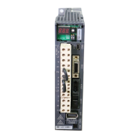
| Category | Controller |
|---|---|
| Manufacturer | Mitsubishi Electric |
| Protection Class | IP20 |
| Type | Programmable Logic Controller (PLC) |
| Input Voltage | 100-240V AC |
| Output Type | Relay, Transistor |
| Programming Language | Ladder Logic, Structured Text |
| Communication Ports | RS-232, RS-485, Ethernet |
| Operating Temperature | 0°C to 55°C |
| Series | MS-T Series |
| Memory Capacity | Varies by model |
| I/O Points | Varies by model |
Highlights critical safety warnings and cautions for proper product handling and operation.
Details standard ambient temperature, humidity, altitude, vibration, and atmosphere requirements.
Provides guidance on measures for using products in environments differing from normal conditions.
Covers ambient conditions, packing, humidity avoidance, and precautions during transport.
Instructions for correct vertical and horizontal mounting, including screw tightening and rail dimensions.
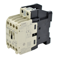
Details coil voltage, terminal screw connection, wiring, and crimp terminal precautions.
Guide for installing additional auxiliary contact blocks (UT-AX4) for contactors.
Instructions for installing mechanical interlock kits to prevent simultaneous contactor operation.
Procedure for mounting surge absorbers to protect against voltage surges.
Illustrates wiring diagrams for various motor types and series, including S-T, S-2xT, TH-T, MSO-T.
Guidance on setting the overload relay's current rating and adjustment procedures.
Explanation of thermal overload relay fusing and coordination with protection devices.
Details the contact configuration (NO/NC) and behavior of the thermal overload relay.