21
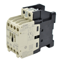
Combination of MSO-T10 (BC), T12 (BC), T20 (BC)
[Applicable magnetic contactor and thermal overload relay]
Combined devices
Magnetic starter
Magnetic
contactor
Thermal
overload relay
Connection
conductor
MSO-T10 S-T10 TH-T18 –
MSO-T12 S-T12 TH-T18 –
MSO-T20 S-T20 TH-T18 –
[Assembly procedure]
1. Loosen the three main terminal screws (2/T1, 4/T2, 6/T3) on the magnetic contactor.
2. Tilt the thermal overload relay, and guide the thermal overload relay’s notch A (two places) into the
magnetic contactor’s indents (two places), and align the position so that the three thermal overload
relay main circuit conductors are on the left side of the main terminal screws. (Fig. 1)
3. Press in the thermal overload relay from the B direction, and insert the thermal overload relay’s
notch A to the magnetic contactor’s indent. (Fig. 2)
4. Turn the thermal overload relay in the direction of arrow C, and turn the thermal overload relay
notch D to the magnetic contactor’s E face. (Fig. 3, 4)
5. Tighten the main terminal screws (2/T1, 4/T2, 6/T3) while pressing the thermal overload relay
toward the magnetic contactor’s side.
[Removal procedures]
1. Loosen the three main terminal screws (2/T1, 4/T2, 6/T3) on the magnetic contactor.
2. Tilt the thermal overload relay and lift it up in the direction of arrow F. Release the joint of the
thermal overload relay notch A and magnetic contactor indent. (Fig. 5)
B
Fig. 2
Fig. 1
Thermal overload relay’s notch A
Thermal overload relay’s main circuit conductor
C
D
E
Fig. 3
Fig. 4
F
Fig. 5
 Loading...