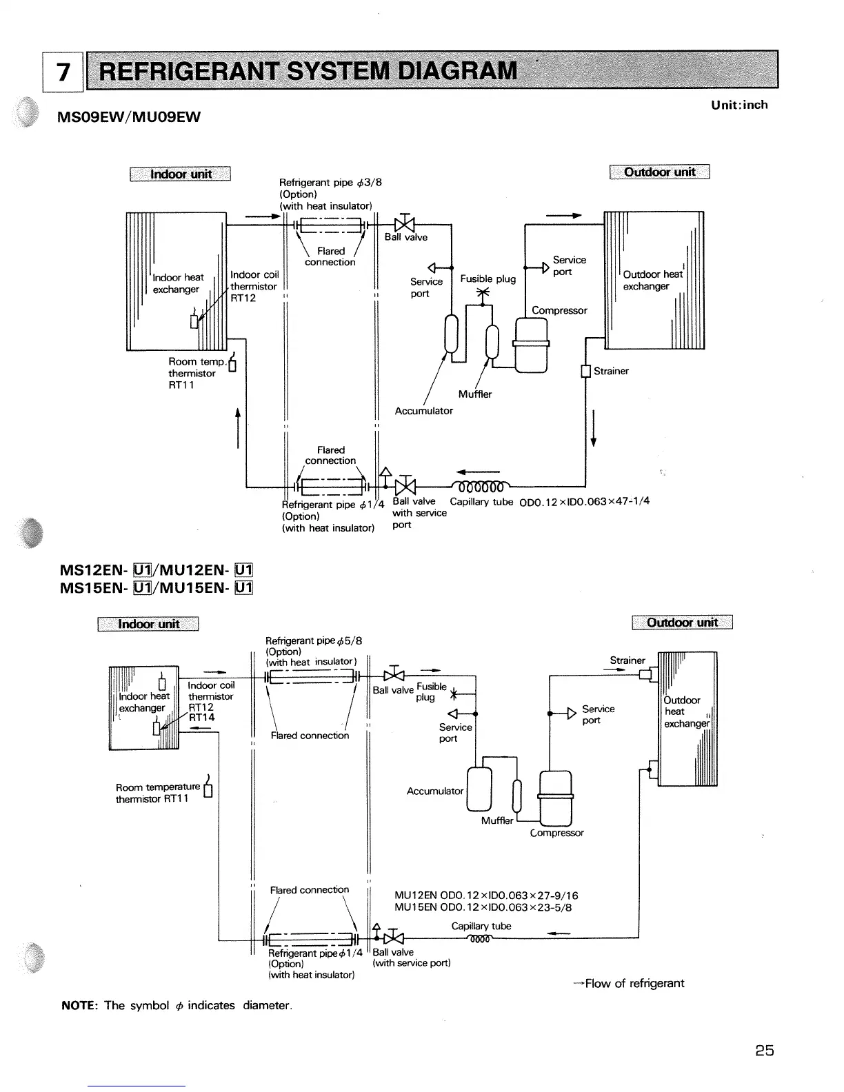
REFRIGERANT SYSTEM DIAGRAM
.
I
Indoorunit
1
Refngerant pipe 43/8
(Opt~on)
(with heat insulator)
connection
1
Unit:
inch
1
Outdoorunit
1
Strainer
i_
I
/I
connection
(I
I
Refrigerant pipe 4 1 /4 Ball valve
Capillary tube 0~0.12 x ID0.063 x47-1/4
(Option) with service
(with heat insulator) port
f
Indoor unit
1
Refnqerant pipe Q5/8
Room temperature
thermistor RTl1
b
I
Service
ared connectio
Accumulator
Muffler
rn
Compressor
I
Outdoor unit
1
Flared connection
MU12EN ODO. 12 xID0.063 X27-9/16
\
I/
MUISEN OD0.12X1D0.063X23-5/8
Refrigerant pipe41 /4
"
Ball valve
(Option) (with service port)
(wkh heat insulator)
+Flow of refrigerant
NOTE:
The symbol
d,
indicates diameter.
 Loading...