Do you have a question about the Mitsubishi Electric MS09NW*2 and is the answer not in the manual?
| Cooling Capacity | 2.5 kW |
|---|---|
| Heating Capacity | 3.2 kW |
| Power Supply | 220-240 V, 50 Hz |
| Indoor Unit Weight | 9.0 kg |
| Indoor Unit Dimensions (W x H x D) | 798 x 295 x 223 mm |
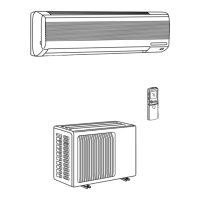
Two indoor units served by a single outdoor unit in a neat, space-saving layout.
Each indoor unit connects to piping up to 49 feet, offering installation freedom.
Restarts equipment automatically after power outage in the previous mode.
Advanced design for lower operating costs and longer service life.
Diagram and labels for the outdoor unit components and connections.
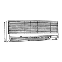
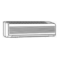
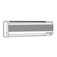
Specifications for the MS09NWX2 indoor unit model.
Specifications for the MUM18NW outdoor unit model.
Details on the wireless remote controller specifications.
Specifications for refrigerant pipe size and connection methods.
Performance data table for single indoor unit operation under various conditions.
Correction factors for cooling capacity based on refrigerant piping length.
Graphs showing cooling capacity and power consumption vs. temperatures.
Graph showing condensing pressure vs. outdoor ambient temperature for different indoor temperatures.
Graph showing suction pressure vs. outdoor ambient temperature for different indoor temperatures.
Overall capacity, SHF, and input for single and double unit operation.
Details on power supply and current for indoor and outdoor units.
Operating data for refrigerant pressures and temperatures.
Data related to indoor unit airflow, temperatures, and fan speed.
Data for outdoor unit fan speed and airflow.
Diagram illustrating power supply connections for the MSM18NW unit.
Power supply ratings and guaranteed voltage ranges for units.
Standard, maximum, and minimum operating temperature and humidity conditions.
Dimensions and layout of the MUM18NW outdoor unit.
Detailed measurements and installation space requirements for the outdoor unit.
Diagram showing minimum clearance needed around the outdoor unit for servicing.
Wiring diagram for the outdoor unit, showing component connections.
Detailed wiring schematic for the MUM18NW outdoor unit.
Key for symbols used in the wiring diagram, listing component names.
Diagram illustrating the refrigerant flow and components for the system.
Refrigerant circuit details for the indoor unit, including pipes and thermistors.
Refrigerant circuit details for the outdoor unit, including compressor and accumulator.
Troubleshooting guide specific to the MUM18NW model.
Important safety and handling precautions before and during troubleshooting.
Methods and criteria for checking the normal/abnormal status of key components.
Troubleshooting flowchart for when compressor and fan fail to operate.
Instructions for disassembling the MUM18NW outdoor unit.
Procedure to remove the valve cover and side panel of the outdoor unit.
Steps to safely remove the fan propeller from the outdoor unit.
List of part numbers and names for the MUM18NW outdoor unit.
Detailed parts list for the MUM18NW outdoor unit with quantity and remarks.
Specifications and part numbers for optional refrigerant extension pipes.