EasyManua.ls Logo

Mitsubishi Electric MSZ-GE50VA2-A1 User Manual

Mitsubishi Electric MSZ-GE50VA2-A1
54 pages
To Next Page IconTo Next Page
Page #1 background imageLoading...
Page #1 background image
CONTENTS
1. TECHNICAL CHANGES ··································· 2
2. PART NAMES AND FUNCTIONS ····················· 3
3. SPECIFICATION ················································ 5
4. NOISE CRITERIA CURVES ······························ 9
5. OUTLINES AND DIMENSIONS ·······················11
6. WIRING DIAGRAM ·········································· 12
7. REFRIGERANT SYSTEM DIAGRAM ············· 14
8. SERVICE FUNCTIONS ··································· 15
9. MICROPROCESSOR CONTROL ··················· 17
10. TROUBLESHOOTING ····································· 25
11. DISASSEMBLY INSTRUCTIONS ···················· 45
SPLIT-TYPE AIR CONDITIONERS
SERVICE MANUAL
INDOOR UNIT
PARTS CATALOG (OBB531)
NOTE:
RoHS compliant products have <G> mark on the spec name plate.
Models
MSZ-GE22VA
-
A1
MSZ-GE50VA
-
A1
MSZ-GE22VAD
-
A1
MSZ-GE50VA2
-
A1
MSZ-GE25VA
-
A1
MSZ-GE50VAD
-
A1
MSZ-GE25VAD
-
A1
MSZ-GE60VA
-
A1
MSZ-GE33VA
-
A1
MSZ-GE60VAD
-
A1
MSZ-GE35VA
-
A1
MSZ-GE71VA
-
A1
MSZ-GE35VA2
-
A1
MSZ-GE71VAD
-
A1
MSZ-GE35VAD
-
A1
MSZ-GE80VA
-
A1
MSZ-GE42VA
-
A1
MSZ-GE80VA2
-
A1
MSZ-GE42VAD
-
A1
MSZ-GE80VAD
-
A1
No. OBH531
REVISED EDITION-E
Please void OBH531 REVISED EDITION-D.
MSZ-GE22VA
MSZ-GE22VAD
MSZ-GE25VA
MSZ-GE25VAD
MSZ-GE33VA
MSZ-GE35VA
MSZ-GE35VA2
MSZ-GE35VAD
MSZ-GE42VA
MSZ-GE42VAD
MSZ-GE50VA
MSZ-GE50VA2
MSZ-GE50VAD
Revision E:
MSZ-GE22VAD-
A1
has been added.
Outdoor unit service manual
MUZ-GE·VA Series (OBH532)
MXZ-A·VA Series (OB447)
MXZ-8A140A (OC316)
MXZ-B•VA (OBH567)
Question and Answer IconNeed help?

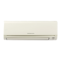
Do you have a question about the Mitsubishi Electric MSZ-GE50VA2-A1 and is the answer not in the manual?

Mitsubishi Electric MSZ-GE50VA2-A1 Specifications

General IconGeneral
TypeSplit System
Cooling Capacity5.0 kW
Heating Capacity6.0 kW
Energy Efficiency Ratio (EER)3.21
Power Supply220-240V, 50Hz
RefrigerantR410A
Outdoor Unit Dimensions (HxWxD)550 x 800 x 285 mm
Weight (Outdoor Unit)35 kg
Noise Level (Outdoor)50 dB

Summary

TECHNICAL CHANGES

PART NAMES AND FUNCTIONS

ACCESSORIES

SPECIFICATION

NOISE CRITERIA CURVES

OUTLINES AND DIMENSIONS

WIRING DIAGRAM

REFRIGERANT SYSTEM DIAGRAM

SERVICE FUNCTIONS

TIMER SHORT MODE

Shortens the compressor start time for service purposes.

P.C. BOARD MODIFICATION FOR INDIVIDUAL OPERATION

Modifies remote controller P.C. boards for individual indoor unit operation.

AUTO RESTART FUNCTION

Unit restarts automatically with previous settings after power interruption.

MICROPROCESSOR CONTROL

WIRELESS REMOTE CONTROLLER

Details the functions and operation of the wireless remote controller.

AUTO VANE OPERATION

Controls horizontal and vertical vane movement for optimal air distribution.

TIMER OPERATION

Setting and releasing of ON/OFF and weekly timers for unit operation.

WEEKLY TIMER OPERATION

Programming daily and weekly operational schedules with temperature settings.

I-SAVE OPERATION

Saves and recalls custom operation settings for user convenience.

EMERGENCY/TEST OPERATION

Manual operation for testing or emergency use without remote controller.

3-MINUTE TIME DELAY OPERATION

Protects the compressor from overload by delaying restart after shutdown.

TROUBLESHOOTING

CAUTIONS ON TROUBLESHOOTING

Important safety and preliminary checks before troubleshooting.

HOW TO REPLACE BATTERIES

Procedure for replacing batteries in the remote controller to resolve malfunctions.

HOW TO INSTALL THE HORIZONTAL VANE

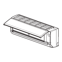
Correct installation procedure for the horizontal vane assembly.

FAILURE MODE RECALL FUNCTION

Recalls and displays memorized abnormal conditions for diagnosis.

INSTRUCTION OF TROUBLESHOOTING

Flowchart guides troubleshooting based on unit symptoms and indicator lights.

TROUBLESHOOTING CHECK TABLE

Lists abnormal points, symptoms, conditions, and remedies for troubleshooting.

TROUBLE CRITERION OF MAIN PARTS

Checks resistance values and conditions of key components for diagnosis.

CHECK OF INDOOR FAN MOTOR

Step-by-step troubleshooting for indoor fan motor errors.

REMOTE CONTROL AND PCB TROUBLESHOOTING

Diagnoses issues related to remote control and indoor electronic control board.

INDOOR PCB AND FAN MOTOR CHECK

Checks indoor P.C. board and fan motor for faults and continuity.

MISWIRING AND SERIAL SIGNAL ERROR CHECK

Procedure to diagnose and resolve miswiring and serial signal communication errors.

HORIZONTAL VANE INSTALLATION CHECK

Verifies correct installation and continuity of the horizontal vane interlock switch.

ELECTROMAGNETIC NOISE DIAGNOSIS

Identifies and provides solutions for electromagnetic noise interference issues.

TEST POINT AND VOLTAGE DIAGRAMS

Provides voltage test points and diagrams for diagnosing electronic components.

DISASSEMBLY INSTRUCTIONS

DISASSEMBLY OF SMALLER MODELS

Instructions for disassembling specific indoor unit models.

DISASSEMBLY OF LARGER MODELS

Instructions for disassembling specific indoor unit models.

Related product manuals