EasyManua.ls Logo

Mitsubishi Electric MUZ-G12SV User Manual

Mitsubishi Electric MUZ-G12SV
116 pages
To Next Page IconTo Next Page
Page #1 background imageLoading...
Page #1 background image
SERVICE MANUAL
CONTENTS
1. TECHNICAL CHANGES ····································2
2. PART NAMES AND FUNCTIONS······················2
3. SPECIFICATION·················································7
4. NOISE CRITERIA CURVES ·····························11
5. OUTLINES AND DIMENSIONS ·······················13
6. WIRING DIAGRAM ··········································17
7. REFRIGERANT SYSTEM DIAGRAM··············21
8. PERFORMANCE CURVES······························24
9. MICROPROCESSOR CONTROL ····················35
10. SERVICE FUNCTIONS·····································63
11. TROUBLESHOOTING······································66
12. DISASSEMBLY INSTRUCTIONS·····················97
13. PARTS LIST····················································106
14. OPTIONAL PARTS·········································115
Wireless type
Models
MSZ-G09SV -
(
WH
)
· MUZ-G09SV -
MSZ-G09SV -
(
WH
)
· MUZ-G09SV -
MSZ-G12SV -
(
WH
)
· MUZ-G12SV -
MSZ-G12SV -
(
WH
)
· MUZ-G12SV -
MSZ-G20SV -
(
WH
)
· MUZ-G20SV -
E1E1
E2E2
E1E1
E2E2
E1E1
No. OB245
REVISED EDITION-B
SPLIT-TYPE, HEAT PUMP AIR CONDITIONERS
Revision:
MSZ-G20SV - has been added.
SPECIFICATION, PERFORMANCE CURVES
and PARTS LIST have been added.
Please void OB245 REVISED EDITION-A.
E1
MSZ-G20SV -
E1
OB245 --1qxp 02.10.22 4:08 PM Page 1

Table of Contents

Question and Answer IconNeed help?

Do you have a question about the Mitsubishi Electric MUZ-G12SV and is the answer not in the manual?

Mitsubishi Electric MUZ-G12SV Specifications

General IconGeneral
BrandMitsubishi Electric
ModelMUZ-G12SV
CategoryAir Conditioner
LanguageEnglish

Summary

TECHNICAL CHANGES

PART NAMES AND FUNCTIONS

INDOOR UNIT COMPONENTS

Identifies and describes components of the indoor unit.

OUTDOOR UNIT COMPONENTS

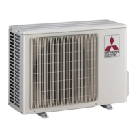
Identifies and describes components of the outdoor unit.

ACCESSORIES

INDOOR UNIT ACCESSORIES

Lists accessories provided for the indoor unit.

OUTDOOR UNIT ACCESSORIES

Lists accessories provided for the outdoor unit.

REMOTE CONTROLLER

SPECIFICATION

INDOOR UNIT SPECIFICATIONS

Details technical specifications for indoor unit models.

OUTDOOR UNIT SPECIFICATIONS

Details technical specifications for outdoor unit models.

SPECIFICATIONS AND RATING CONDITIONS OF MAIN ELECTRIC PARTS

INDOOR UNIT MAIN ELECTRIC PARTS

Lists specifications and rating conditions for indoor unit main electric parts.

OUTDOOR UNIT MAIN ELECTRIC PARTS

Lists specifications and rating conditions for outdoor unit main electric parts.

NOISE CRITERIA CURVES

OUTLINES AND DIMENSIONS

MSZ-G09SV INDOOR UNIT DIMENSIONS

Shows dimensional drawings and outlines for the MSZ-G09SV indoor unit.

MSZ-G12SV INDOOR UNIT DIMENSIONS

Shows dimensional drawings and outlines for the MSZ-G12SV indoor unit.

OUTDOOR UNIT DIMENSIONS

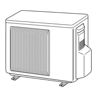
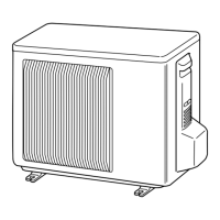
Shows dimensional drawings and outlines for outdoor units.

MSZ-G20SV INDOOR UNIT DIMENSIONS

Shows dimensional drawings and outlines for the MSZ-G20SV indoor unit.

MUZ-G20SV OUTDOOR UNIT DIMENSIONS

Shows dimensional drawings and outlines for the MUZ-G20SV outdoor unit.

WIRING DIAGRAM

INDOOR UNIT MODELS WIRING DIAGRAM

Provides wiring diagrams for indoor unit models.

OUTDOOR UNIT MODELS WIRING DIAGRAM

Provides wiring diagrams for outdoor unit models.

REFRIGERANT SYSTEM DIAGRAM

MSZ-G09SV INDOOR UNIT REFRIGERANT DIAGRAM

Shows the refrigerant system for MSZ-G09SV indoor units.

MUZ-G09SV OUTDOOR UNIT REFRIGERANT DIAGRAM

Shows the refrigerant system for MUZ-G09SV outdoor units.

MSZ-G12SV INDOOR UNIT REFRIGERANT DIAGRAM

Shows the refrigerant system for MSZ-G12SV indoor units.

MUZ-G12SV OUTDOOR UNIT REFRIGERANT DIAGRAM

Shows the refrigerant system for MUZ-G12SV outdoor units.

MSZ-G20SV INDOOR UNIT REFRIGERANT DIAGRAM

Shows the refrigerant system for MSZ-G20SV indoor unit.

MUZ-G20SV OUTDOOR UNIT REFRIGERANT DIAGRAM

Shows the refrigerant system for MUZ-G20SV outdoor unit.

MAX. REFRIGERANT PIPING LENGTH

Details maximum refrigerant piping lengths and sizes.

MAX. HEIGHT DIFFERENCE

ADDITIONAL REFRIGERANT CHARGE (R22:g)

PERFORMANCE CURVES

INDOOR UNIT PERFORMANCE CURVES

Displays performance curves for the indoor unit.

OUTDOOR UNIT PERFORMANCE CURVES

Displays performance curves for the outdoor unit.

HOW TO MEASURE INDOOR AIR TEMPERATURE DIFFERENCE

Explains how to measure temperature differences for performance analysis.

OUTDOOR LOW PRESSURE AND OUTDOOR UNIT CURRENT

COOL OPERATION LOW PRESSURE AND CURRENT

Details low pressure and current for cool operation.

HEAT OPERATION LOW PRESSURE AND CURRENT

Details low pressure and current for heat operation.

MICROPROCESSOR CONTROL

WIRELESS REMOTE CONTROLLER FUNCTIONS

Explains the functions and operation of the wireless remote controller.

INDOOR UNIT DISPLAY SECTION INDICATORS

Describes the indoor unit display section and operation indicators.

“I FEEL CONTROL” OPERATION MODES

Details the "I FEEL CONTROL" operation mode and its features.

TEMPERATURE BUTTONS AND FUZZY CONTROL

COOL MODE OF “I FEEL CONTROL”

FAN SPEED AND FROST PREVENTION IN COOL MODE

Details fan speed control and frost prevention in COOL mode.

DRY MODE OF “I FEEL CONTROL”

FAN SPEED AND COMPRESSOR CONTROL IN DRY MODE

Details fan speed and compressor control in DRY mode.

HEAT MODE OF “I FEEL CONTROL”

FAN SPEED, COLD AIR, WARM AIR, AND FLOW SOFT CONTROLS

Explains fan speed, cold air prevention, warm air, and flow soft controls in HEAT mode.

TIME CHART OF DEFROSTING IN HEAT MODE

FAN MOTOR CONTROL

ROTATIONAL FREQUENCY FEEDBACK CONTROL

Explains feedback control for fan motor rotational frequency.

FAN MOTOR LOCK-UP PROTECTION

Describes the protection mechanism for fan motor lock-up.

AUTO VANE OPERATION

HORIZONTAL VANE OPERATION

Details the operation and control of the horizontal vane.

VANE AUTO MODE OPERATION

Explains automatic vane angle determination for optimal distribution.

DEW PREVENTION FOR VANE

Explains dew prevention function for vane angle adjustment.

SWING MODE OPERATION

Details the vertical vane swing mode operation.

HORIZONTAL AIR FLOW CONTROL

Explains horizontal airflow control via the SWING button.

COLD AIR PREVENTION IN HEAT OPERATION

Details vane angle changes for cold air prevention in HEAT operation.

ECONO COOL OPERATION

SWING OPERATION IN ECONO COOL

Details swing operation characteristics within ECONO COOL mode.

TIMER OPERATION

HOW TO SET THE TIMER

Provides step-by-step instructions for setting the timer.

TIMER CANCEL FUNCTION

Explains how to cancel timer settings.

PROGRAM TIMER

EMERGENCY-TEST OPERATION

OPERATIONAL FREQUENCY CONTROL OF OUTDOOR UNIT

OUTDOOR UNIT OPERATIONAL FREQUENCY OUTLINE

Outlines the operational frequency control of the outdoor unit.

FREQUENCY CONTROL BY ROOM/SET TEMPERATURE DIFFERENCE

Explains frequency control based on room and set temperature difference.

FREQUENCY CONTROL BY ESTIMATED DISCHARGE TEMPERATURE

OPTIMAL VOLTAGE CONTROL

OPTIMAL VOLTAGE CONTROL CONCEPT

Explains the concept of optimal voltage control for the compressor.

HOW TO DETERMINE THE OPTIMAL VOLTAGE

Details how to determine the optimal voltage for compressor efficiency.

EXPANSION VALVE CONTROL (LEV CONTROL)

OUTLINE OF LEV CONTROL

Explains the basic control mechanisms of the expansion valve (LEV).

LEV STANDARD SPECIFICATION AND OPERATION

Details standard specifications and general operation of LEV control.

LEV OPENING CORRECTION BY DISCHARGE TEMPERATURE

Explains LEV opening correction based on discharge temperature.

OUTDOOR FAN MOTOR CONTROL

R.V. COIL CONTROL

INDOOR FAN MOTOR CONTROL

CIRCUIT BLOCK DIAGRAM FOR FAN MOTOR CONTROL

Shows the circuit block diagram for indoor fan motor control.

CONTROL SYSTEM FOR FAN MOTOR

Explains the control system logic for the indoor fan motor.

“I FEEL CONTROL” OPERATION

WIRELESS REMOTE CONTROLLER FUNCTIONS

Explains the functions and operation of the wireless remote controller.

INDOOR UNIT DISPLAY SECTION INDICATORS

Describes the indoor unit display section and operation indicators.

OPERATION TIME CHARTS

Illustrates operation time charts for various modes.

COOL MODE OF “I FEEL CONTROL”

FAN SPEED AND FROST PREVENTION IN COOL MODE

Details fan speed control and frost prevention in COOL mode.

TEMPERATURE BUTTONS AND FUZZY CONTROL

Explains temperature control buttons and fuzzy control logic.

DRY MODE OF “I FEEL CONTROL”

FAN SPEED AND COMPRESSOR CONTROL IN DRY MODE

Details fan speed and compressor control in DRY mode.

HEAT MODE OF “I FEEL CONTROL”

FAN SPEED, COLD AIR, WARM AIR, AND FLOW SOFT CONTROLS

Explains fan speed, cold air prevention, warm air, and flow soft controls in HEAT mode.

WARM AIR CONTROL IN HEAT MODE

FLOW SOFT CONTROL

OUTDOOR FAN CONTROL

OUTDOOR FAN SPEED SWITCHING

Explains outdoor fan speed control based on ambient temperature.

COMPRESSOR FREQUENCY AND FAN SPEED RELATIONSHIP

Shows the relationship between compressor frequency and fan speed.

HIGH PRESSURE PROTECTION

DISCHARGE TEMPERATURE PROTECTION

DEFROSTING CONDITIONS

R.V. COIL CONTROL

DEFROSTING TIME CHART IN HEAT MODE

COOL OPERATION

DRY OPERATION

HEAT OPERATION

FAN MOTOR CONTROL

ROTATIONAL FREQUENCY FEEDBACK CONTROL

Explains feedback control for fan motor rotational frequency.

FAN MOTOR LOCK-UP PROTECTION

Describes the protection mechanism for fan motor lock-up.

AUTO VANE OPERATION

HORIZONTAL VANE OPERATION

Details the operation and control of the horizontal vane.

VANE AUTO MODE OPERATION

Explains automatic vane angle determination for optimal distribution.

DEW PREVENTION FOR VANE

Explains dew prevention function for vane angle adjustment.

SWING MODE OPERATION

Details the vertical vane swing mode operation.

HORIZONTAL AIR FLOW CONTROL

Explains horizontal airflow control via the SWING button.

COLD AIR PREVENTION IN HEAT OPERATION

Details vane angle changes for cold air prevention in HEAT operation.

ECONO COOL OPERATION

SWING OPERATION IN ECONO COOL

Details swing operation characteristics within ECONO COOL mode.

LONG MODE OPERATION

VERTICAL VANE OPERATION

TIMER OPERATION

HOW TO SET THE TIMER

Provides step-by-step instructions for setting the timer.

TIMER CANCEL FUNCTION

Explains how to cancel timer settings.

PROGRAM TIMER

EMERGENCY-TEST OPERATION

MAIN POWER SUPPLY CIRCUIT

OUTLINE DRAWING OF MAIN POWER SUPPLY

Shows the outline drawing of the main power supply circuit.

OUTLINE OF MAIN POWER SUPPLY CIRCUIT

Explains the main power supply circuit structure.

POWER FACTOR IMPROVEMENT OF POWER SUPPLY

Explains power factor improvement for the power supply.

ELIMINATION OF ELECTRICAL NOISE

Details the elimination of electrical noise.

INTELLIGENT POWER MODULE (IPM)

Explains the Intelligent Power Module (IPM).

OPERATIONAL FREQUENCY CONTROL OF OUTDOOR UNIT

OUTDOOR UNIT OPERATIONAL FREQUENCY OUTLINE

Outlines the operational frequency control of the outdoor unit.

FREQUENCY CONTROL BY ROOM/SET TEMPERATURE DIFFERENCE

Explains frequency control based on room and set temperature difference.

FREQUENCY CONTROL BY ESTIMATED DISCHARGE TEMPERATURE

OPTIMAL VOLTAGE CONTROL

OPTIMAL VOLTAGE CONTROL CONCEPT

Explains the concept of optimal voltage control for the compressor.

HOW TO DETERMINE THE OPTIMAL VOLTAGE

Details how to determine the optimal voltage for compressor efficiency.

EXPANSION VALVE CONTROL (LEV CONTROL)

OUTLINE OF LEV CONTROL

Explains the basic control mechanisms of the expansion valve (LEV).

LEV STANDARD SPECIFICATION AND OPERATION

Details standard specifications and general operation of LEV control.

LEV OPENING CORRECTION BY DISCHARGE TEMPERATURE

Explains LEV opening correction based on discharge temperature.

HEAT DEFROSTING CONTROL

CONDITIONS TO ENTER DEFROSTING MODE

Lists conditions required to enter heat defrosting mode.

DEFROSTING OPERATION

Details the defrosting operation sequence.

CONDITIONS TO FINISH DEFROSTING MODE

Lists conditions required to finish defrosting mode.

DISCHARGE TEMPERATURE PROTECTION CONTROL

COMPRESSOR ON/OFF CONTROL

Explains compressor ON/OFF control based on discharge temperature.

COMPRESSOR OPERATION FREQUENCY CONTROL

Details compressor operation frequency control based on discharge temperature.

OUTDOOR FAN CONTROL

OUTDOOR FAN SPEED SWITCHING

Explains outdoor fan speed control based on operating units and frequency.

COMPRESSOR FREQUENCY AND FAN SPEED RELATIONSHIP

Shows the relationship between compressor frequency and fan speed.

RELATION BETWEEN MAIN SENSOR AND ACTUATOR

SERVICE FUNCTIONS

CHANGE IN DEFROST SETTING

Explains how to change the defrost setting by modifying a jumper wire.

TIMER SHORT MODE

Describes the TIMER SHORT MODE for service purposes.

P.C. BOARD MODIFICATION FOR INDIVIDUAL OPERATION

Details P.C. board modifications for individual unit operation with multiple controllers.

REMOTE CONTROLLER P.C. BOARD MODIFICATION

AUTO RESTART FUNCTION

HOW TO SET AUTO RESTART FUNCTION

Explains the procedure to enable the AUTO RESTART FUNCTION.

TROUBLESHOOTING

CAUTIONS ON TROUBLESHOOTING

Provides safety precautions and checks before troubleshooting.

TROUBLESHOOTING PROCEDURE

Outlines the general steps for troubleshooting.

HOW TO REPLACE BATTERIES

Provides instructions on how to replace remote controller batteries.

INSTRUCTION OF TROUBLESHOOTING

TROUBLESHOOTING CHECK TABLE

INDOOR UNIT TROUBLESHOOTING

A table listing indoor unit troubleshooting symptoms and checks.

INDOOR UNIT SELF CHECK TABLE

Details self-check symptoms, detection methods, and checkpoints for indoor units.

OUTDOOR UNIT TROUBLESHOOTING

TROUBLE CRITERIA OF MAIN PARTS

COMPRESSOR TROUBLE CRITERIA

Lists criteria for diagnosing compressor issues.

INDOOR FAN MOTOR TROUBLE CRITERIA

Lists criteria for diagnosing indoor fan motor issues.

INNER FUSE AND PROTECTOR CRITERIA

Lists criteria for inner fuse and protector issues.

MOTOR AND SENSOR PART CRITERIA

Lists criteria for motor and sensor components.

HOW TO CHECK INVERTER/ COMPRESSOR

CHECK OF OPEN PHASE

Method to check for open phase in the inverter/compressor.

CHECK OF TRANSISTOR MODULE

Procedure to check the transistor module.

CHECK OF COMPRESSOR

CHECK OF COMPRESSOR WINDING

Procedure to check the compressor winding resistance.

CHECK OF COMPRESSOR OPERATION TIME

Procedure to measure compressor operation time for diagnosis.

CHECK OF INDOOR FAN MOTOR

CHECK OF REMOTE CONTROLLER AND RECEIVER P.C. BOARD

CHECK OF OUTDOOR THERMISTORS

CHECK OF INDOOR ELECTRONIC CONTROL P.C. BOARD

CHECK OF OUTDOOR POWER SUPPLY

CHECK OF R.V. COIL

CHECK OF OUTDOOR FAN MOTOR

CHECK OF POWER SUPPLY

CHECK OF THERMAL FUSE

CHECK OF RUSH CURRENT LIMITING CIRCUIT

CHECK OF EXPANSION VALVE (LEV)

HOW TO CHECK MIS-WIRING AND SERIAL SIGNAL ERROR

CHECK OF INDOOR FAN MOTOR

CHECK OF REMOTE CONTROLLER AND RECEIVER P.C. BOARD

CHECK OF INDOOR ELECTRONIC CONTROL P.C. BOARD

CHECK OF OUTDOOR POWER SUPPLY

HOW TO CHECK MIS-WIRING

CHECK OF R.V. COIL

CHECK OF LEV

CHECK OF INVERTER/ COMPRESSOR

CHECK OF OUTDOOR THERMISTOR

CHECK OF OUTDOOR FAN MOTOR

TEST POINT DIAGRAM AND VOLTAGE

INDOOR ELECTRONIC CONTROL P.C. BOARD TEST POINTS

Shows test points and voltage measurements for the indoor P.C. board.

POWER MONITOR, RECEIVER P.C. BOARD TEST POINTS

Shows test points for the power monitor/receiver P.C. board.

MSZ-G20SV INDOOR ELECTRONIC CONTROL P.C. BOARD DIAGRAM

RECEIVER P.C. BOARD DIAGRAM

Provides a test point diagram for the receiver P.C. board.

OUTDOOR ELECTRONIC CONTROL P.C. BOARD DIAGRAM

MUZ-G20SV OUTDOOR ELECTRONIC CONTROL P.C. BOARD DIAGRAM

NOISE FILTER P.C. BOARD DIAGRAM

MUZ-G20SV NOISE FILTER P.C. BOARD DIAGRAM

RELAY P.C. BOARD DIAGRAM

DISASSEMBLY INSTRUCTIONS

INDOOR UNIT - REMOVING THE FRONT PANEL

Instructions for removing the indoor unit front panel.

INDOOR UNIT - REMOVING ELECTRONIC CONTROL P.C. BOARD

Instructions for removing the indoor unit's electronic control and receiver P.C. boards.

INDOOR UNIT - ELECTRICAL BOX AND MOTOR REMOVAL

INDOOR UNIT - REMOVING THE ELECTRICAL BOX

Instructions for removing the electrical box from the indoor unit.

INDOOR UNIT - REMOVING THE VANE MOTOR

Instructions for removing the indoor unit's vane motor.

INDOOR UNIT - REMOVING THE FAN AND FAN MOTOR

Instructions for removing the indoor unit's fan and fan motor.

MSZ-G20SV INDOOR UNIT DISASSEMBLY

REMOVING THE FRONT PANEL (INDOOR UNIT)

Instructions for removing the front panel of the MSZ-G20SV indoor unit.

REMOVING P.C. BOARDS (INDOOR UNIT)

Instructions for removing P.C. boards from the indoor unit.

INDOOR UNIT - ELECTRICAL BOX AND MOTOR REMOVAL

REMOVING THE ELECTRICAL BOX (INDOOR UNIT)

Instructions for removing the electrical box from the indoor unit.

REMOVING THE VANE MOTOR (INDOOR UNIT)

Instructions for removing the indoor unit's vane motor.

REMOVING THE FAN AND FAN MOTOR (INDOOR UNIT)

Instructions for removing the indoor unit's fan and fan motor.

OUTDOOR UNIT DISASSEMBLY

REMOVING THE CABINET (OUTDOOR UNIT)

Instructions for removing the outdoor unit cabinet.

REMOVING THE INVERTER ASSEMBLY (OUTDOOR UNIT)

Instructions for removing the outdoor unit inverter assembly.

REMOVING THE NOISE FILTER P.C. BOARD (OUTDOOR UNIT)

Instructions for removing the outdoor unit noise filter P.C. board.

REMOVING THE RELAY P.C. BOARD (OUTDOOR UNIT)

Instructions for removing the outdoor unit relay P.C. board.

REMOVING THE ELECTRONIC CONTROL P.C. BOARD (OUTDOOR UNIT)

Instructions for removing the outdoor unit electronic control P.C. board.

OUTDOOR UNIT COMPONENT REMOVAL

REMOVING THE OUTDOOR FAN MOTOR

Instructions for removing the outdoor unit fan motor.

REMOVING THE COMPRESSOR

Instructions for removing the compressor and related components.

MUZ-G20SV OUTDOOR UNIT DISASSEMBLY

REMOVING THE BACK PANEL (OUTDOOR UNIT)

Instructions for removing the outdoor unit's back panel.

REMOVING THE INVERTER ASSEMBLY (OUTDOOR UNIT)

Instructions for removing the outdoor unit inverter assembly.

REMOVING THE ELECTRONIC CONTROL P.C. BOARD (OUTDOOR UNIT)

Instructions for removing the outdoor unit electronic control P.C. board.

REMOVING THE NOISE FILTER (OUTDOOR UNIT)

Instructions for removing the outdoor unit noise filter.

OUTDOOR UNIT COMPONENT REMOVAL

REMOVING THE R.V. COIL (OUTDOOR UNIT)

Instructions for removing the outdoor unit R.V. coil.

REMOVING DEFROST AND DISCHARGE TEMPERATURE THERMISTOR

Instructions for removing defrost and discharge temperature thermistors.

REMOVING THE FIN TEMPERATURE THERMISTOR

Instructions for removing the fin temperature thermistor.

REMOVING THE OUTDOOR FAN MOTOR

Instructions for removing the outdoor unit fan motor.

REMOVE THE COMPRESSOR AND 4-WAY VALVE

PARTS LIST

INDOOR UNIT STRUCTURAL PARTS

Lists structural parts for the indoor unit with part numbers.

INDOOR UNIT HEAT EXCHANGER PARTS

Lists heat exchanger parts for the indoor unit.

INDOOR UNIT FUNCTIONAL PARTS AND ELECTRICAL PARTS

ACCESSORY AND REMOTE CONTROLLER

OUTDOOR UNIT STRUCTURAL PARTS AND FUNCTIONAL PARTS

OUTDOOR UNIT ELECTRICAL PARTS

INDOOR UNIT STRUCTURAL PARTS

INDOOR UNIT HEAT EXCHANGER

INDOOR UNIT FUNCTIONAL PARTS AND ELECTRICAL PARTS

ACCESSORY AND REMOTE CONTROLLER

OUTDOOR UNIT STRUCTURAL PARTS AND FUNCTIONAL PARTS

OUTDOOR UNIT ELECTRICAL PARTS

AIR CLEANING FILTER

DEODORIZING FILTER

OPTIONAL PARTS

AIR CLEANING FILTER (OPTIONAL)

Details the optional air cleaning filter.

DEODORIZING FILTER (OPTIONAL)

Details the optional deodorizing filter.

DRAIN SOCKET (OPTIONAL)

Describes the optional drain socket and its installation.

Related product manuals