EasyManua.ls Logo

Mitsubishi Electric MUZ-GE25VA User Manual

Mitsubishi Electric MUZ-GE25VA
70 pages
To Next Page IconTo Next Page
Page #1 background imageLoading...
Page #1 background image
SERVICE MANUAL
CONTENTS
1. TECHNICAL CHANGES ··································· 3
2. PART NAMES AND FUNCTIONS ····················· 4
3. SPECIFICATION ················································ 5
4. NOISE CRITERIA CURVES ······························ 7
5. OUTLINES AND DIMENSIONS ························ 9
6. WIRING DIAGRAM ···········································11
7. REFRIGERANT SYSTEM DIAGRAM ············· 18
8. PERFORMANCE CURVES ····························· 21
9. ACTUATOR CONTROL ··································· 40
10. SERVICE FUNCTIONS ···································· 41
11. TROUBLESHOOTING ····································· 41
12. DISASSEMBLY INSTRUCTIONS ···················· 61
Models
SPLIT-TYPE AIR CONDITIONERS
NOTE:
RoHS compliant products have <G> mark on the spec name plate.
HFC
utilized
R410A
No. OBH516
REVISED EDITION-D
OUTDOOR UNIT
Indoor unit service manual
MSZ-GE•VA Series (OBH515)
MSZ-CGE•VA Series (OBH523)
PARTS CATALOG (OBB516)
MUZ-GE25VA
MUZ-GE35VA
MUZ-GE42VA
Revision D:
• Changing defrost finish temperature has
been corrected (10-1.).
Please void OBH516 REVISED EDITION-C.
MUZ-GE25VA -
E1
MUZ-GE50VA -
E1
MUZ-GE25VAH -
E1
MUZ-GE50VAH -
E1
MUZ-GE35VA -
E1
MUZ-GE60VA -
E1
MUZ-GE35VAH -
E1
MUZ-GE71VA -
E1
MUZ-GE42VA -
E1
MUZ-GE42VAH -
E1
Question and Answer IconNeed help?

Do you have a question about the Mitsubishi Electric MUZ-GE25VA and is the answer not in the manual?
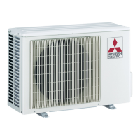
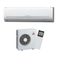
Mitsubishi Electric MUZ-GE25VA Specifications

General IconGeneral
TypeSplit System Air Conditioner
Cooling Capacity2.5 kW
Heating Capacity3.2 kW
Power Supply220-240 V, 50 Hz
Indoor Unit Dimensions (W x H x D)798 x 295 x 232 mm
Outdoor Unit Dimensions (W x H x D)800 x 550 x 285 mm
Weight (Indoor Unit)9 kg
RefrigerantR410A
Indoor Unit Weight9 kg
Noise Level (Outdoor Unit)49 dB(A)

Summary

Specifications

Outlines and Dimensions

Wiring Diagram

Refrigerant System Diagram

Performance Curves

Service Functions

Troubleshooting

Cautions on Troubleshooting

Important safety and procedural notes before starting troubleshooting.

Failure Mode Recall Function

Procedures for recalling and interpreting fault codes.

Troubleshooting Check Table

Lists symptoms, LED indications, conditions, and remedies for faults.

Trouble Criterion of Main Parts

Criteria for checking the normal operation of key components.

Troubleshooting Flow

Step-by-step diagnostic flowcharts for various components.

Test Point Diagram and Voltage

Diagrams showing test points and voltage values on the inverter P.C. board.

Disassembly Instructions

Related product manuals