EasyManua.ls Logo

Mitsubishi Electric MUZ-WR18NA User Manual

Mitsubishi Electric MUZ-WR18NA
60 pages
To Next Page IconTo Next Page
Page #1 background imageLoading...
Page #1 background image
Models
MUZ-WR09NA
-
U1
,
U2
MUZ-WR12NA
-
U1
,
U2
MUZ-WR18NA
-
U1
,
U2
MUZ-WR24NA
-
U1
HFC
utilized
R410A
MUZ-WR24NA
PARTS CATALOG (OBB819)
SERVICE MANUAL
No. OBH819
REVISED EDITION-B
Indoor unit service manual
MSZ-WR•NA Series (OBH818)
CONTENTS
1. TECHNICAL CHANGES ······························2
2. PART NAMES AND FUNCTIONS ··················3
3. SPECIFICATION ········································4
4. OUTLINES AND DIMENSIONS ·····················7
5. WIRING DIAGRAM ·····································9
6. REFRIGERANT SYSTEM DIAGRAM ··········· 12
7. DATA······················································ 15
8. ACTUATOR CONTROL ····························· 25
9. SERVICE FUNCTIONS ······························ 26
10. TROUBLESHOOTING ······························· 27
11. DISASSEMBLY INSTRUCTIONS ················· 52
OUTDOOR UNIT
OBH819 REVISED EDITION-A is void.
Revision B:
MUZ-WR09/12/18NA-
U2
have been added.
• 10-4. The resistant value of the defrost
heater has been corrected.
Question and Answer IconNeed help?

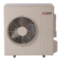
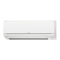
Do you have a question about the Mitsubishi Electric MUZ-WR18NA and is the answer not in the manual?

Mitsubishi Electric MUZ-WR18NA Specifications

General IconGeneral
BrandMitsubishi Electric
ModelMUZ-WR18NA
CategoryAir Conditioner
LanguageEnglish

Summary

1 TECHNICAL CHANGES

3 SPECIFICATION

8 ACTUATOR CONTROL

9 SERVICE FUNCTIONS

10 TROUBLESHOOTING

10-1. CAUTIONS ON TROUBLESHOOTING

Important safety and handling precautions before starting troubleshooting.

10-2. FAILURE MODE RECALL FUNCTION

How to recall and interpret memorized failure modes for diagnosis.

10-3. TROUBLESHOOTING CHECK TABLE

A table listing symptoms, LED indications, conditions, and remedies for troubleshooting.

10-4. TROUBLE CRITERION OF MAIN PARTS

Specifies resistance and voltage criteria for testing major components.

10-5. TROUBLESHOOTING FLOW

Detailed step-by-step procedures for diagnosing and resolving unit malfunctions.

10-6. TEST POINT DIAGRAM AND VOLTAGE

Diagrams and test points for the inverter P.C. board, including thermistor resistance charts.

11 DISASSEMBLY INSTRUCTIONS

Related product manuals