Do you have a question about the Mitsubishi Electric MUZ-WR12NA-U2 and is the answer not in the manual?
| Cooling Capacity | 12, 000 BTU/h |
|---|---|
| Heating Capacity | 13, 600 BTU/h |
| Refrigerant | R410A |
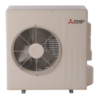
| Outdoor Unit Dimensions (HxWxD) | 21-5/8 x 31-1/2 x 11-5/8 inches |
| COP (Heating) | 3.8 |
| Operating Temperature (Cooling) | 14°F to 115°F |
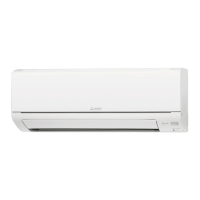
| Indoor Unit Dimensions (HxWxD) | 11-5/8 x 33-1/8 x 9-1/8 inches |
| Power Supply | 208 / 230 V, 1 Phase, 60 Hz |
Lists standard operating parameters for different models.
Essential safety precautions and preliminary checks before troubleshooting.
A comprehensive table of symptoms, LED indicators, conditions, and remedies.
Specifies resistance and operational criteria for key components.
Diagnostic flowcharts for troubleshooting various operational issues.
Visual guide to test points and voltage measurements on the inverter P.C. board.