EasyManua.ls Logo

Mitsubishi Electric MUZ-WR18NA-U2 User Manual

Mitsubishi Electric MUZ-WR18NA-U2
60 pages
To Next Page IconTo Next Page
Page #1 background imageLoading...
Page #1 background image
Models
MUZ-WR09NA
-
U1
,
U2
MUZ-WR12NA
-
U1
,
U2
MUZ-WR18NA
-
U1
,
U2
MUZ-WR24NA
-
U1
HFC
utilized
R410A
MUZ-WR24NA
PARTS CATALOG (OBB819)
SERVICE MANUAL
No. OBH819
REVISED EDITION-B
Indoor unit service manual
MSZ-WR•NA Series (OBH818)
CONTENTS
1. TECHNICAL CHANGES ······························2
2. PART NAMES AND FUNCTIONS ··················3
3. SPECIFICATION ········································4
4. OUTLINES AND DIMENSIONS ·····················7
5. WIRING DIAGRAM ·····································9
6. REFRIGERANT SYSTEM DIAGRAM ··········· 12
7. DATA······················································ 15
8. ACTUATOR CONTROL ····························· 25
9. SERVICE FUNCTIONS ······························ 26
10. TROUBLESHOOTING ······························· 27
11. DISASSEMBLY INSTRUCTIONS ················· 52
OUTDOOR UNIT
OBH819 REVISED EDITION-A is void.
Revision B:
MUZ-WR09/12/18NA-
U2
have been added.
• 10-4. The resistant value of the defrost
heater has been corrected.
Question and Answer IconNeed help?

Do you have a question about the Mitsubishi Electric MUZ-WR18NA-U2 and is the answer not in the manual?
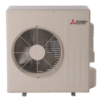
Mitsubishi Electric MUZ-WR18NA-U2 Specifications

General IconGeneral
Heating Capacity20, 000 BTU/h
Seasonal Energy Efficiency Ratio (SEER)20.5
Power Supply208/230V, 1-Phase, 60Hz
RefrigerantR410A
HSPF10.5
Voltage208 / 230V
Operating Temperature (Cooling)14°F to 115°F
Operating Temperature (Heating)-13°F to 75°F

Summary

OUTDOOR UNIT SERVICE MANUAL

1 TECHNICAL CHANGES

3 SPECIFICATION

4 OUTLINES AND DIMENSIONS

5 WIRING DIAGRAM

6 REFRIGERANT SYSTEM DIAGRAM

MAX. REFRIGERANT PIPING LENGTH and MAX. HEIGHT DIFFERENCE

ADDITIONAL REFRIGERANT CHARGE (R410A: oz.)

Table and calculation for additional refrigerant charge based on piping length.

7 DATA

7-4. STANDARD OPERATION DATA

Standard operation data for capacity, input, and components.

7-5. CAPACITY AND INPUT CORRECTION BY INVERTER OUTPUT FREQUENCY

Correction factor graphs for capacity and input based on inverter frequency.

7-6. HOW TO OPERATE FIXED-FREQUENCY OPERATION (Test run operation)

Steps for performing a fixed-frequency test run operation.

8 ACTUATOR CONTROL

9 SERVICE FUNCTIONS

10 TROUBLESHOOTING

10-2. FAILURE MODE RECALL FUNCTION

Functionality and procedures for recalling stored failure modes.

10-3. TROUBLESHOOTING CHECK TABLE

Table listing common symptoms, LED indications, conditions, and remedies.

10-4. TROUBLE CRITERION OF MAIN PARTS

Criteria for checking main parts like thermistors, compressor, and motors.

10-5. TROUBLESHOOTING FLOW

Flowcharts for diagnosing various components and system issues.

10-6. TEST POINT DIAGRAM AND VOLTAGE

Diagrams showing test points and voltage readings on the inverter PC board.

11 DISASSEMBLY INSTRUCTIONS

2. Removing the inverter assembly, inverter P.C. board

Steps to remove the inverter assembly and PC board.

6. Removing the compressor and 4-way valve

Steps to remove the compressor and 4-way valve.

Related product manuals