Do you have a question about the Mitsubishi Electric MUZ-WR24NA-U1 and is the answer not in the manual?
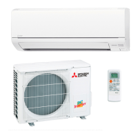
| Cooling Capacity | 24, 000 BTU/h |
|---|---|
| Energy Efficiency Ratio (EER) | 11.5 |
| Seasonal Energy Efficiency Ratio (SEER) | 20.5 |
| Refrigerant | R410A |
| Operating Temperature (Cooling) | 14°F to 115°F |
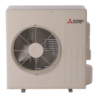
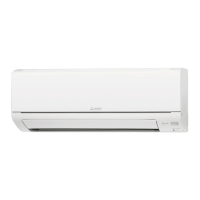
| Type | Split System |
| Power Supply | 208/230V, 60Hz |
| Outdoor Unit Dimensions (W x H x D) | 33-7/16 x 13 inches |
Outlines essential precautions and checks before performing troubleshooting.
Explains how to retrieve stored error codes and failure modes.
Provides a table linking LED indications to abnormal points, conditions, and remedies.
Lists resistance criteria for testing main electrical components.
Offers detailed flowcharts for diagnosing specific issues like compressor or fan problems.
Shows test points and voltage measurements on the inverter P.C. board.