Do you have a question about the Mitsubishi Electric MXZ-2F33VF4-E1 and is the answer not in the manual?
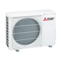
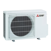
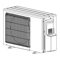
Lists all compatible outdoor unit models covered in this service manual.
Details of the latest revision 'L' for the service manual.
Critical warning against using incorrect refrigerants to prevent unit damage or fire.
Safety guidelines to follow while performing repairs on the unit.
Specific modifications and additions made in Revision A.
Specific modifications and additions made in Revision L.
Specific safety measures when working with R32 refrigerant.
Explanation of various safety symbols found on the air conditioner unit.
List of tools recommended and exclusive for R32 refrigerant service.
Precautions and flowchart for determining if existing pipes can be reused.
Ensuring sufficient space and ventilation to maintain safety standards.
List of accessories provided with the outdoor unit.
Detailed technical specifications for the outdoor unit models.
Electrical characteristics including power input and current ratings.
Details regarding the compressor's model, output, and oil.
Required clearances around the outdoor unit for proper installation and ventilation.
Specifies the maximum allowable lengths for refrigerant piping based on unit configuration.
Step-by-step guide for charging refrigerant based on model and indoor unit configuration.
Procedure to safely remove refrigerant before unit relocation or disposal.
Key parameters to read and procedure for measuring temperature differences.
Information on setting DIP switches for various service functions.
Procedure to activate or deactivate the low standby power mode.
How to activate and check the automatic line correction feature.
General safety precautions to be followed during troubleshooting.
How to recall and interpret stored failure codes for diagnostics.
Procedure for checking the inverter and compressor for proper operation.
Diagnostic steps for when the outdoor unit fails to operate.
Diagrams showing test points and voltages on the inverter P.C. board.
Diagrams showing test points and voltages on the outdoor control P.C. board.
Step-by-step guide to remove the outer panels and cabinet of the unit.
Procedure for removing the compressor and the 4-way valve.
| Cooling Capacity | 3.3 kW |
|---|---|
| Power Supply | 220-240 V, 50 Hz |
| Refrigerant | R32 |
| Indoor Unit Noise Level | Data varies depending on the connected indoor unit model. |
| Outdoor Unit Noise Level | 46 dB(A) |
| Outdoor Unit Dimensions (WxHxD) | 550 x 285 mm |