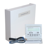
Flow temp. controller
C-13
Electrical work (FTC)
Flow temp. controller
3
C-13
3.4.2 EXTERNAL INPUT ( analog signal ) 4-20mA / 1-5V / 0-10V
Connect the transmission cables to No. 3 and 4 on the terminal block (TB62).
No. 3 on the terminal block(TB62) : Plus side
No. 4 on the terminal block(TB62) : Minus side (Reference side)
Switch setting
Input Outdoor unit SW1-1 SW1-2 SW1-5 SW1-6 SW6-1 SW6-2
4-20mA SPLIT type OFF ON OFF OFF ON ON
PACKAGED type OFF ON ON OFF ON ON
1-5V SPLIT type OFF ON OFF OFF OFF ON
PACKAGED type OFF ON ON OFF OFF ON
0-10V SPLIT type ON ON OFF OFF OFF OFF
PACKAGED type ON ON ON OFF OFF OFF
4-20mA / 1-5V / 0-10V setting
Caution:
The external input signals are separated by basic insulation from power supply for the unit.
The external input signals should be separated by supplementary insulation from where user may touch in case that it is installed
where user may touch.
Connect the terminals by using the ring terminals and also insulate the cables of adjoining terminals when wiring to terminal block.
3.5. Connecting external output (Photo. 3-5)
TB141 Item OFF ON
1-2 (OUT1) X1 Operation Output OFF ON
3-4 (OUT2) X2 Error Output Normal Error
5-6 (OUT3) X3 Comp. Output OFF ON
7-8 (OUT4) X4 Defrost Output OFF ON
9-10 (OUT5) X5 Mode(Cooling) Output OFF ON
11-12 (OUT6) X6 Mode(Heating/HeatingECO/Hot Water/ Anti-Freeze) Output OFF ON
13-14 (OUT7) X7 — — —
Note :
External output signals are separated by basic insulation from other circuit of interface.
Caution :
When 2 or more external outputs are used, the power supply on the output side should be the same.
3.6. Wiring specifi cation of External output / External input
Locally supplied parts
Item Name Model and specifi cations
External output
function
External output signal
wire
Use sheathed vinyl coated cord or cable.
Max. 50m
Wire type : CV, CVS or equivalent
Wire size : Stranded wire 0.5mm
2
to 1.25mm
2
Solid wire:
{
0.65mm to
{
1.2mm
Display lamp, etc. Non-voltage Contact AC220-240V (DC30V), 1A or less
*Connect the surge absorber according to the load at site.
External input
function
External input signal
wire
Use sheathed vinyl coated cord or cable.
Max. 10m
Wire type :CV, CVS or equivalent
Wire size : Stranded wire 0.5mm
2
to 1.25mm
2
Solid wire :
{
0.65mm to
{
1.2mm
Switch Non-voltage "a" contact signals
Remote switch : minimum applicable load DC 12V, 1mA
Photo.3-5
TB141
FTCAt site
6
5
2
1
4
3
TB62
4-20mA/1-5V/0-10V
(
Wired remote controller
(
+
0mA -- 4mA --------------- 20mA
0V-------1V------------------- 5V
0V------------------10V
No.1 Temp.
Stop
4-20mA
Refer to the section 8 for details about No1, 2 Temp.
The selectable set temperature range depends on SW1-7, 8.
1-5V
0-10V
No.2 Temp.
FLOW TEMP.
ANALOG
SIGNAL
1FTC
TB141
At site
X1
2 3
X2
4 5
X3
6 7
X4
8 9
X5 X6 X7
1413121110
3 5 7 9 11 131
42
TB141
6 8 10 12 14
 Loading...