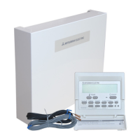
Flow temp. controller
C-30
Before test run (FTC)
Flow temp. controller
5
C-30
FTC
5.1. Check
After completing installation and the wiring and piping of the local application and outdoor units, check for refrigerant leakage, looseness in the
power supply or control wiring, wrong polarity, and no disconnection of one phase in the supply.
Use a 500-volt megohmmeter to check that the resistance between the power supply terminals and ground is at least 1.0MΩ.
Warning:
Do not use the system if the insulation resistance is less than 1.0MΩ.
Caution:
Do not carry out this test on the control wiring (low voltage circuit) terminals.
5.2. Self-check
1
Turn on the power.
2
Press [CHECK] button twice.
3
Press [CHECK] button twice to fi nish self-check.
A
CHECK button
B
IC : FTC unit OC : Outdoor unit
C
Check code
Check code Symptom
P1 Flow water (TH1) sensor error
P2 Refrigerant liquid Pipe (TH2) sensor error
P6 Freezing/Overheating protection operation
Fb FTC unit control system error (memory error, etc.)
E0~E5 Signal transmission failure between remote controller and FTC.
E6~EF Signal transmission failure between outdoor unit and FTC.
– – – – No trouble generated in the past.
FFFF No corresponding unit
U*, F* Outdoor unit failure. Refer to the outdoor unit wiring diagram.
For description of each LED(LED1~5) provided on the FTC, refer to the following table.
LED 1 (Power for microcomputer) Indicates whether control power is supplied. Make sure that this LED is always lit.
LED 2 (Power for remote controller) Indicates whether power is supplied to the remote controller. This LED lights only in the case of the FTC
unit which is connected to the outdoor unit refrigerant address “0“.
LED 3 (Communication between FTC and outdoor unit) Indicates state of communication between the FTC and outdoor unit. Make sure that this LED is always
blinking.
LED 4 —
LED 5 —
ON/OFF
TEMP.
ERROR CODE
 Loading...