13
S1
S2
S3
L
N
L
N
BLACK
BLACK
YELLOW
YELLOW
YELLOW
YELLOW
BLACK
BLACK
CNO1
CNO1
CNO1
White
CNO1
White
FTC
(Master)
FTC
(Master)
S1
S2
S3
Initial settings
(Power supplied
by outdoor unit)
Modified settings
(Separate power
supply to
FTC(Master))
Power
supply
~/N
230V
50Hz
Earth
leakage
breaker
*1
*1
*1
*1
Wiring
circuit
breaker
or
Isolating
switch
L
N
S1
S2
S3
Outdoor unit
S1
S2
S3
TB2
TB1
L
N
ECB
Wiring
circuit
breaker
or
Isolating
switch
To control
board
ELB for
immersion
heater
(DHW tank)
L
N
Power
supply
~/N
230V
50Hz
Earth
leakage
breaker
Wiring
circuit
breaker
or
Isolating
switch
Power
supply
circuit
circuit
: PAC-IF061B-E
: PAC-IF062/063B-E
FTC (Master)
Power
supply
3N~
400V
50Hz
Earth
leakage
breaker
Wiring
circuit
breaker
or
Isolating
switch
L3
L2
L1
N
S1
S2
S3
Outdoor unit
S1
S2
S3
TB2
TB1
L
N
ECB
Wiring
circuit
breaker
or
Isolating
switch
To control
board
ELB for
immersion
heater
(DHW tank)
L
N
Power
supply
~/N
230V
50Hz
Earth
leakage
breaker
Wiring
circuit
breaker
or
Isolating
switch
Power
supply
circuit
circuit
FTC (Master)
4. Electrical work
Option 2: FTC (Master) powered by independent source
If FTC (Master) and outdoor units have separate power supplies, the following
requirements MUST be carried out:
•FTC(Master)unitelectrical boxconnectorconnectionschanged. (see
Fig. 4.1.3)
•OutdoorunitDIPswitchsettingschangedtoSW8-3ON.
•TurnontheoutdoorunitbeforetheFTC(Master).
•Powerbyindependent source isnotavailablefor particular modelsof
outdoor unit model.
For more detail, refer to the connecting outdoor unit installation manual.
<Fig. 4.1.3>
<Fig. 4.1.5>
Electrical connections 1 phase/3 phase
FTC (Master) power supply ~/N 230 V 50 Hz
FTC (Master) input capacity
Main switch (Breaker)
*1
16 A
Wiring
Wiring No.
× size (mm²)
FTC (Master) power supply 2 × Min. 1.5
FTC (Master) power supply earth 1 × Min. 1.5
FTC (Master) - Outdoor unit *2 2 × Min. 0.3
FTC (Master) - Outdoor unit earth —
Circuit
rating
FTC (Master) L - N *3 230V AC
FTC (Master) - Outdoor unit S1 - S2 *3 —
FTC (Master) - Outdoor unit S2 - S3 *3 24V DC
*2. Max. 120 m
*3. The values given in the table above are not always measured against the
ground value.
Notes:
1. Wiring size must comply with the applicable local and national codes.
2.
FTC(Master)unit/outdoorunitconnectingcordsshallnotbelighter
thanpolychloroprenesheathedexiblecord.(Design60245IEC57)
FTC
(Master)
unit power supply cords shall not be lighter than
polychloroprenesheathedexiblecord.(Design60227IEC53)
3. Install an earth longer than other cables.
4.
Please keep enough output capacity of power supply for each individual
heater.Insufcientpowersupplycapacitymightcausechattering.
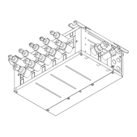
TB2
Clamps
Slot
TB1
Clamps
1 2 3 4 5
Notes:1.Donotrunthelowvoltagecablesthroughaslotthatthehighvoltagecablesgothrough.
2.Donotrunothercablesexceptlowvoltagecablesthroughaslotthatthewirelessreceiver’scablegoesthrough.
3.Donotbundlepowercablestogetherwithothercables.
4.Bundlecablesasgureabovebyusingclamps.
*1 If the installed earth leakage circuit breaker does not have an over-current protection function, install a breaker with that function along the same power line.
A breaker with at least 3.0 mm contact separation in each pole shall be provided. Use earth leakage breaker (NV).
The breaker shall be provided to ensure disconnection of all active phase conductors of the supply.
Note:InaccordancewithIEEregulationsthecircuitbreaker/isolatingswitchlocatedontheoutdoorunitshouldbeinstalledwithlockabledevices(healthandsafety).
<Fig.4.1.4>WiringforPAC-IF062/063B-E
1
High voltage cables (OUTPUT)
2
High voltage cables (OUTPUT)
3
Low voltage cables (INPUT) and
wireless receiver’s cable
4
Thermistor cables
5
Power cables
Clamps
Clamps
<3 phase><1 phase>
 Loading...