Do you have a question about the Mitsubishi Electric PLFY-P12NFMU-E and is the answer not in the manual?
| Brand | Mitsubishi Electric |
|---|---|
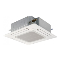
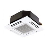
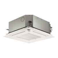
| Model | PLFY-P12NFMU-E |
| Category | Air Conditioner |
| Language | English |
Safety guidelines for handling R410A refrigerant and associated tools.
Important cautions and procedures to follow during service operations.
Overview of the PAR-32MAA wired remote controller and its functions.
Detailed explanation of the functions and buttons of the PAR-32MAA remote controller.
Technical specifications for the indoor unit models.
Troubleshooting steps and error codes for system abnormalities.
Methods for checking the functionality of various parts.
Graphs showing thermistor resistance versus temperature.
Details on LEV operation, pulse signals, and troubleshooting common issues.
Procedure for checking the DC fan motor and indoor controller board.