EasyManua.ls Logo

Mitsubishi Electric PLFY-P32VCM-E User Manual

Mitsubishi Electric PLFY-P32VCM-E
32 pages
To Next Page IconTo Next Page
Page #1 background imageLoading...
Page #1 background image
TECHNICAL & SERVICE MANUAL
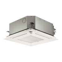
Indoor unit
[Model names] [Service Ref.]
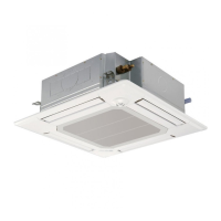
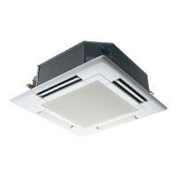
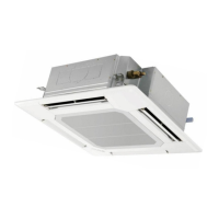
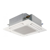
PLFY-P20VCM-E.TH
PLFY-P20VCM-E1.TH
PLFY-P25VCM-E.TH
PLFY-P25VCM-E1.TH
PLFY-P32VCM-E.TH
PLFY-P32VCM-E1.TH
PLFY-P40VCM-E.TH
PLFY-P40VCM-E1.TH
INDOOR UNIT
CONTENTS
1. TECHNICAL CHANGES·························2
2. SAFETY PRECAUTION··························2
3. PART NAMES AND FUNCTIONS··········6
4. SPECIFICATIONS···································8
5. 4-WAY AIR FLOW SYSTEM·················10
6. OUTLINES AND DIMENSIONS············12
7. WIRING DIAGRAM·······························13
8.
REFRIGERANT SYSTEM DIAGRAM
·····14
9. DISASSEMBLY PROCEDURE·············15
10. TROUBLESHOOTING··························18
11. PARTS LIST··········································25
12. RoHS PARTS LIST·······························29
SPLIT-TYPE, HEAT PUMP AIR CONDITIONERS
R407C
R22
R410A
Model name
indication
No.OC314
REVISED EDITION-C
Revision :
PLFY-P20/25/32/40VCM-
E1.TH are added in
REVISED EDITION-C.
Some descriptions have
been modified.
PLFY-P20VCM-E
PLFY-P25VCM-E
PLFY-P32VCM-E
PLFY-P40VCM-E
Please void OC314
REVISED EDITION-B.
July 2007
Note :
• RoHS compliant products
have <G> mark on spec
name plate.
For servicing RoHS compli-
ant products, refer to the
RoHS Parts List.
OC314C--1.qxp 07.7.19 8:42 AM Page 1

Other manuals for Mitsubishi Electric PLFY-P32VCM-E

Questions and Answers:

Mitsubishi Electric PLFY-P32VCM-E Specifications

General IconGeneral
BrandMitsubishi Electric
ModelPLFY-P32VCM-E
CategoryAir Conditioner
LanguageEnglish

Summary

SAFETY PRECAUTION

Refrigerant Handling Precautions

Safety guidelines for handling new refrigerants, including R407C and R410A.

PART NAMES AND FUNCTIONS

Indoor Unit Components

Identifies key parts of the indoor unit, such as intake, filter, and vanes.

Wired Remote Controller Display and Controls

Explains the various indicators and controls on the wired remote control unit.

SPECIFICATIONS

General Model Specifications

Details performance and physical characteristics for different models.

Electrical Parts Specifications

Lists electrical components and their specifications for each model.

WIRING DIAGRAM

REFRIGERANT SYSTEM DIAGRAM

DISASSEMBLY PROCEDURE

Initial Component Removal

Steps for safely removing the air intake grille, fan guard, panels, and electrical parts.

TROUBLESHOOTING

Component Verification and Fault Diagnosis

Guide to checking parts resistance and diagnosing common operational faults.

TEST POINT DIAGRAM

Related product manuals